VFD created static

Status
Not open for further replies.
First off, as the others have said, grounding is CRITICAL to a good VFD installation. The NEC grounding requirements are only about safety, grounding requirements for VFDs are more stringent and if you get sloppy, you get problems. Ground wire back to the VFD from the motor is the most important thing, never rely on just the conduit (assuming steel), even though the NEC says that's OK.

Then next, the output cables will broadcast a signal if left unshielded. The shielding can be STEEL conduit, but if you ran cable without a shield or PVC conduit, you have a radio broadcast antenna. If it is anything other than steel conduit making the VFD to motor connection, use shielded VFD cable and ground BOTH ands of the shield, not just one end (that only applies to signal and control wiring). You are creating a "faraday cage" around the conductors, you need solid grounding of that "cage".

Last issue is the line side conductors, which can also broadcast noise. IF the outputs are all correct and you still have the noise, then you need an EMI/RFI filter. Whether or not it is a Franklin or Pentair pump, you can get an EMI/RFI filter for the line side of any VFD from people like TCI, Schaffner, MTE etc.
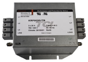
 
If it is anything other than steel conduit making the VFD to motor connection, use shielded VFD cable and ground BOTH ands of the shield, not just one end (that only applies to signal and control wiring). You are creating a "faraday cage" around the conductors, you need solid grounding of that "cage".
...
Do they make a VFD cable for submersible well pumps?
 
Do they make a VFD cable for submersible well pumps?
Not sure, I've not seen it, but Franklin implies in some of its literature that it might exist because they recommend it for "EMC sensitive applications". In general though, the down-hole cables are underground and not likely to be causing troubles. If there are separate wires going from the VFD to a terminal box at the top of a down-hole pump, then those should be shielded But is it submersible? He didn't say it was. Lots of well pumps have the pump above ground.
 
For VFDs the ferrite beads can get quite large and expensive.

The ferrite will have a common mode choking effect; you don't want to choke the capacitive return current, so in this case the ferrite should enclose the circuit conductors and the ground from motor to VFD.

Jon

If you enclose the phase conductors AND ground by definition, it does nothing because the sum of all four is zero.
 
For VFDs the ferrite beads can get quite large and expensive.

The ferrite will have a common mode choking effect; you don't want to choke the capacitive return current, so in this case the ferrite should enclose the circuit conductors and the ground from motor to VFD.

Jon

193abba11a0a0f1fe341575ddfac0112.jpg


How is this for large? 900 HP AB Powerflex 755 with about 200 feet of shielded cable to the motor. MASSIVE common mode problems. Clocking 90 A peaks without the filter, 40 A with. Insulated bearing AND grounding brush. Losing bearings from fluting every few months. Still looking to improve this but we’ve cut it in half. We believe the cores are saturating. Other than the pathetic original load reactors this crappy drive had zilch for output filtering. What a piece of garbage.

Those are NOT ferrites. Those would not withstand the current. Those are nanocrystalline steel with 80,000 permeability. The little ones are MH&Ws idea of an EMC filter. They think we might be getting capacitively coupling which I’m not buying but on this run I didn’t have a spectrum analyzer to see what is going on.

For perspective this is about 5 miles down the road from the old NASCAR Rockingham speedway on a dryer fan.
 
How is this for large? 900 HP AB Powerflex 755 with about 200 feet of shielded cable to the motor. MASSIVE common mode problems. Clocking 90 A peaks without the filter, 40 A with. Insulated bearing AND grounding brush. Losing bearings from fluting every few months. Still looking to improve this but we’ve cut it in half. We believe the cores are saturating.
...
Those are NOT ferrites. Those would not withstand the current. Those are nanocrystalline steel with 80,000 permeability. The little ones are MH&Ws idea of an EMC filter. They think we might be getting capacitively coupling which I’m not buying but on this run I didn’t have a spectrum analyzer to see what is going on.
And those smaller toroids would be more likely to saturate because with a single conductor there's no cancellation of its magnetic field by a current flowing in the opposite direction.
 
And those smaller toroids would be more likely to saturate because with a single conductor there's no cancellation of its magnetic field by a current flowing in the opposite direction.

Exactly. A far better design for those would have switched out the load reactors for a dv/dt filter (LC differential mode filter) which takes care of reflections and EMI and keep the CM filter but I needed support from MH&W and the little ones aren’t doing any harm so I’m humoring them. Each of the rings is a 1 turn common mode inductor. So there is about 100 microhenries there. It pains me not to wrap the cables through since the inductance is proportional to the square of the turns. Even two passes makes it equal 4 of these. But they would have saturated and trying to do anything with 12/C 500 MCM coarse strand that has heat set is not easy.
 
If you enclose the phase conductors AND ground by definition, it does nothing because the sum of all four is zero.

I agree with you on the physics, but disagree with you on 'does nothing'.

If you enclose the phase and ground conductors then you create impedance against common mode current on the complete set, meaning impedance against ground current returning by paths other than the selected/enclosed ground. This should help with coupling from the VFD cable to other systems.

But it wouldn't help at all in the situation you described with bearing currents and the like. It won't reduce the path from VFD to winding to frame to ground and back to the VFD.

Have you considered the grounding brushes that shunt the current around the bearings?

Jon
 
I want to amplify that the ground between the VFD and the motor frame is _critical_.

The way VFDs work, the entire motor winding gets 'switched' between the positive and negative DC rail at the PWM switching frequency. This creates _huge_ ground current spikes through capacitive coupling of the motor winding to the motor frame. These current spikes need to return to the VFD, and if the path taken to the VFD doesn't closely follow the path of the power conductors, then these high frequency currents will radiate.

-Jon
Thanks, but this may be next to impossible since the motor is several hundred feet in the ground and doesn’t have provisions for grounding.
 
250.112C & M. The submersible motor frame and and any metal well casing must have an equipment grounding conductor. We've been doing this since the 1980's. If we pulled a submersible pump that didn't have an EGC, we have been required to add one. All water well submersible pump motors being sold in the USA have had EGC's for more than the last 30 years. That's one of things that electrical inspectors specifically look at in my state.
 
I don't think a pump motor 100' down a well in a grounded metal casing is going to radiate much, OTOH the wires from the VFD to the well-head could easily.

That’s not the point. The ground is a required return path for VFDs or they get very noisy capacitively coupling to everything around them.
 
My truck radios, tuned to 880, don't get noisey until I hit the garage approach. Unfortunately, that puts me about equidistant from the well underground and the vfd itself.

You may also try an output filter if you can’t fix the installation error (no ground). Either a common mode filter (see Cool Blue by MH&W) or an EMC filter as others mentioned (MH&W sells a generic one) as well. This is generally done to solve a different issue (bearing fluting) but is done to eliminate capacitively coupled voltages and ground currents. YMMV though
 
You may also try an output filter if you can’t fix the installation error (no ground). Either a common mode filter (see Cool Blue by MH&W) or an EMC filter as others mentioned (MH&W sells a generic one) as well. This is generally done to solve a different issue (bearing fluting) but is done to eliminate capacitively coupled voltages and ground currents. YMMV though
I have an EG plus it’s in metallic conduit for the first 20’ before changing to PVC on out to the riser, then standard well cable down 230’. At the time I thought the metallic raceway would be enough. Load reactor plus an EMI/RFI general purpose filter on the input that was added later.

I see that an RF filter is available for less than $30. Now, input or output, that is the question.
 
Use a portable AM radio to see which is radiating more interference?
My first choice would be the output.
But the high frequency pulsed voltage might fry a filter not intended for that application

Sent from my Pixel 4a using Tapatalk
 
Status
Not open for further replies.
Top