voltage drop calculation

Status
Not open for further replies.

eeeee

Member
Location
Alaska
My colleague and I thought we would point out a concern we have with the two different methods of doing a voltage drop calculation and see if the forum would agree with us:

Method I, VD=(2KXLXI)/Cm, where K is a constant based on conductor property and temperature in the cable; L is length one-way; I is current; cm is cross sectional area. Note that no power factor is assumed in this equation-this is a little upsetting to us.

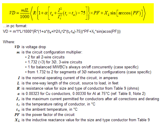
Method II, VD=vXIXRcos(theta) + Xsin(theta), where theta is the power factor:R is resistance of the cable:X is reactance of the cable. Here there is no concern for the K value of the cable.

We compared our calculated result using equation method I against the voltage drop tables and found a significant result that we feel could lead to a different cable size selection based on the value selected for voltage drop. We know the voltage drop tables must have been derived using a computer program that uses one of the two methods to calculate voltage drop.

My colleagues" concern is that it is imperative that the right wire size is selected in the end obviously should loads be used that are not suited for the selected wire size.
 

jtester

Senior Member
Location
Las Cruces N.M.
Method 1 is an approximation, method 2 is more exact. You're right that method 1 doesn't include pf or circuit reactance. EE's are trained in school to use method 2. Unless you are pretty sure of a pf and a circuit reactance, you'll be guessing about those values.

As an electrical engineer also, I encourage you to use the most accurate method at your disposal. I use method #2 on all calculations, but only vary pf on medium voltage calculations because I don't have firm info on typical lower voltage pf's.

As Homer Simpson once said, "Every time I learn something new, something old gets pushed out of my head." and E=IZ is much easier for me to remember than method 1.

Jim T
 

Snorks

Member
Hi eeeee,

The lower formula is the IEEE exact formula and is the only VD formula that can be verfied with a site measurement.

Vd = V + I*R*cos(theta) + I * X * sin(theta) - square root(V2 - (I * X * cos(theta) - I * R * sin(theta))^2)

You'll also need to account for ambient temperature.

And, there are software packages available that perform voltage drop with this formula that will make this task a lot easier.
 

W6SJK

Senior Member
I once complained to a major site for electricians about the lack of PF in the calcs on the site. They said electricians don't care about PF. I hope they never use the site for long feeders! Of course, then why would they be looking at vdrop if that was the case!
 

Smart $

Esteemed Member
Location
Ohio
Snorks said:
...The lower formula is the IEEE exact formula and is the only VD formula that can be verfied with a site measurement.

Vd = V + I*R*cos(theta) + I * X * sin(theta) - square root(V2 - (I * X * cos(theta) - I * R * sin(theta))^2)

You'll also need to account for ambient temperature.

And, there are software packages available that perform voltage drop with this formula that will make this task a lot easier.
Umm... I believe you missed a "power" caret between V and 2. In equation form is that...

VDIEEE.gif


When you say exact, is this formula the latest version? This is the first time I've seen the formula as such. Previously it's always been given as V = IRcosθ + IXsinθ.

(BTW, I see you asked me a question about this issue in another thread on voltage drop... please accept my apology for not responding... I entirely missed it until now. I'll continue here rather than bumping the other thread...)

The first question I have on that formula is: Where are the values for R and X obtained? If from a table in the "red book", are the values in NEC Table 9 identical? Being an electrician, I, and others like myself, are of the impression we have to restrict our calculations to the scope of the NEC (i.e. not engineer without a license to do so).

So is there an exact method to adjust for ambient temperature with this formula?

Additionally, I don't see any adjustment built into the formula for adjusting conductor temperature. As you most likely know, resistance varies with current. Table 9 "R" values are values for conductors at 75?C. That would be conducting at 100% ampacity if the conductors are rated 75?C. How often are we permitted by NEC requirements to operate a circuit continuously at 75?C? Isn't the answer something like "next to never". So how is this formula considered to be exact? ...or is it that it's exact as long as one uses the appropriate "R" value... and determining the appropriate "R" value is left as an exercise for the user :rolleyes:

Anyway, combining several published formulas and staying within the scope of the NEC, I derived the following voltage drop formula, based mostly on V = IRcosθ + IXsinθ...

VDformula.gif
 
Last edited:
Status
Not open for further replies.
Top