voltage drop clarification

Status
Not open for further replies.

ocoee

Member
Location
Golden Co
I am posting again to see who may reply, I posted yesterday It seems by the time several people chime in ( thank you) the original question gets lost or watered down.

Here the input for my voltage drop Calc.
1. 277/480V 3P 4W
2. K value 12.9 for CU
3. distance is 500' from sub panel to service( underground in PVC)
4 load at the end of the circuit is 177 amps per phase
5. wire selected 300MCM


Here is my math VD= 1.73 . 12.9 . 177 . 500/300,000
VD=6.58 or 2.3% line to N
VD=6.58 or 1.3% line to line

Question 1 is this valid?
Question 2 is the method the project engineer uses (below) more accurate?


How he does it. Thank you all for your input! Happy holidays!

1. Using the voltage and current and the formula R = V / I, calculate the resistance in your circuit that would result in 100% VD.
2. Determine what voltage drop is acceptable as a percentage and multiply the value from Step 1 by that number. For example 2% would be 0.02 x R = Total Allowable Circuit Resistance
3. In order to get to the ohms/1000ft given in Table 8 of Chapter 9 in the NEC, we then need to figure out how many 1000 ft sections we have in our circuit. If, as in this situation, we?re estimating the distance to be 500 ft from line to load, the math is easy. Our circuit is 500 ft out the line and 500 ft back along the neutral. That?s one 1000 ft section. Had it been 250 ft we?d be at only half of a 1000 ft section and so the resistance in the wire could be twice as much and have the circuit resistance stay the same.
4. Then all that?s left is do divide the number from Step 2 by the number from Step 3 and compare it to the NEC.

In our case then,
R Total = 277 / 175 = 1.583 ohms
R Allowable = 1.5% * 1.583 = 0.0237 ohms
D = 530 * 2 = 1060 ft.
L = D / 1000 = 1.06 thousand ft
Conductor Resistance = 0.0237 / 1.06 = 0.0224 ohms/1000ft

Looking at Table 8, we then see that we need a wire of 600 MCM.

Digging a bit deeper, Table 8 is really for DC. The AC table is Table 9, but it?s for uncoated conductors only. Looking at the impact coating has on DC conductors of this size, there appears to be about a 4.2% kicker. If we can translate that over to the AC table, it looks like our 600 MCM coated becomes 0.02397 ohms/1000 ft and is therefore too high for our needs. We?d either need to go to a 700 MCM or allow the higher voltage drop (1.61% by my calculations).

Please either find fault in my calculation or provide your own to this detail. I?m afraid I still can?t determine where your numbers are coming from.
 

gar

Senior Member
Location
Ann Arbor, Michigan
Occupation
EE
101226-1318 EST

ocoee:

I can only partially answer your question.

When you use any canned formula you need to understand any assumptions upon which that formula is based.

Note: you are using different values for current and length in the two halves of your post. But those differences are insignificant relative to your question.

And second you are using different voltage drop percentages between the two halves.

If we assume your load is a 3 phase Y with only one phase loaded, then the engineer's approach is valid. Except I do not know anything about the referenced tables, would require a library visit.

My calculations using your first values of 177 A per phase and 500 ft, and your second half requirement of 1.5% drop, and my assumption of only one phase loaded produces:

Loop length 1000 ft.

Wire resistance at 177 A load for 1.5% drop assuming everything is resistive and fully unbalanced is
R = (277*0.015)/177 = 0.0235 ohms for 1000 ft of wire.

If you had a balanced 3 phase load, then the resistance per hot phase wire would be 0.0235 ohms. Same as above, but now over a 500 ft length because in the balanced condition there is no current in the neutral, and therefore no voltage drop. Now the wire size is based on 0.0489 ohms per 1000 ft.

At 20 deg C the resistance of annealed copper is 0.09827 ohms/1000 ft for #0. This is 105,500 circular mils. To get to 0.0235 ohms requires an area of (0.09827/0.0235)*105,500 = 4.182*105,500 = about 441,000 circular mils. This has to be increased based on the actual wire temperature allowed at full load (resistance increases with temperature --- limitation is the insulation on the wire), and skin resistance effect at 60 Hz (resistance increases with frequency). The tables you refer to should cover these factors.

If you have a balanced load, then your wire circular mil area will be about 1/2 the totally unbalanced wire size.

.
 

ocoee

Member
Location
Golden Co
design peramaters

design peramaters

Thank you,

I understand now what he is doing, or at least it is sinking in. I apologize the two parts of the post had different inputs, So thank you for taking time to make sense of it.

I would be grateful for your opinion on the big picture as I am trying to filter through lot info from different sources.

So here it is basically, We will be combining the output of 21 solar/grid tie inverters. They are 277V single phase outputs. combined on a 277/480 4 wire sub panel. 530 feet back to the service. Seven per phase .approx 177 amps per phase. The solar arrays are identical IE. effectively no shading, same tilt and orientation. They should produce the same outputs.
I understand over time they will degrade at different rates, may have some soiling,or a module, or inverter could go bad. Since the customer will be paid on production, we would like to be as efficient as possible. I would prefer not to over-do it. Seem like the 700 mcm he would like to use is way too big for the load.

What constitutes significant imbalance?
should I design for voltage drop based on balanced phases?
should I design based on the single phase voltage drop? or something in between?

Thanks
Geoff. PS. I am new to this forum
 

gar

Senior Member
Location
Ann Arbor, Michigan
Occupation
EE
101226-1537 EST

ocoee:

I think you should assumed a balanced system. It should be near that a majority of the time. I do not known whether you are close to the wire rating, but I doubt it.

Assuming that voltage drop is the primary criteria, then a 1% voltage drop is a waste of 1% of your generated power. Suppose you can sell this power for $0.10/KWH, and there are 1800 productive hours per year, then per KW wasted there is lost revenue of $180/year. In a balanced system with a 1% voltage drop with 277 V and 177 A the loss per year based on $0.10/KWH is about 277*177*0.01*180 = $2446.

Look at wire cost and a reasonable payback period, maybe 5 years, and see what you learn.

Check my logic and calculations, and substitute real world numbers. Then see what the numbers tell you.

.
 

Smart $

Esteemed Member
Location
Ohio
...

Please either find fault in my calculation or provide your own to this detail. I’m afraid I still can’t determine where your numbers are coming from.
First, there is no one prescribed method for calculating voltage drop. Most of the basic methods, such as the one you are using, end up with some "padding" to be on the safe side in actual use.

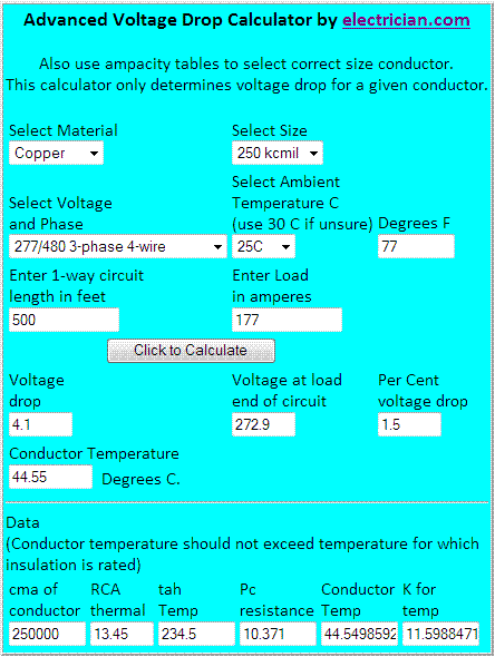
For your situation I used this online calculator (scroll down for the calculator). The article explains much of why others are "basic". For example, your calculation uses k=12.9... but k is only equal to 12.9 when the conductor's operating temperature is 75?C. In using upsized conductors to compensate for Vd, the conductors will never reach an operating temperature of 75?C.

The following image is a capture of the values inputted and returned by the calcualtor referenced. Note the value for k in the lower right corner.

Vdcalc.gif


...And while this calculator is called an advanced calculator, it only compensates for conductor and ambient temperatures as far as I can tell. It does not compensate for buried versus in-open-air thermal losses, nor does it compensate for the type of conduit used, power factor, skin effect, and others factors, and uses a general value for proximal heating effect.... meaning there is no adjustment for the number of conductors in the grouping.

As for the engineer's method, it is a roundabout way to determine Vd using the RID calculation, as I call it: Vd = (2 or 1.732)?R?I?D?1000. The problem I see with his calc' is that he is not giving any credit for the system operating as a 3? system. Under max' generating conditions, there is no Vd on the neutral. Should we assume there will be a nominal operating condition where only one bank of the PV system will be generating at max' output while the other banks will be at zero output? I think not.
 
Last edited:

ocoee

Member
Location
Golden Co
Thank you! I will check voltage drop against dollar per kwh and the pay back period and system budget.


Happy new year!

regards Goeff
 

Smart $

Esteemed Member
Location
Ohio
...

Assuming that voltage drop is the primary criteria, then a 1% voltage drop is a waste of 1% of your generated power. Suppose you can sell this power for $0.10/KWH, and there are 1800 productive hours per year, then per KW wasted there is lost revenue of $180/year. In a balanced system with a 1% voltage drop with 277 V and 177 A the loss per year based on $0.10/KWH is about 277*177*0.01*180 = $2446.

...

Check my logic and calculations, and substitute real world numbers. Then see what the numbers tell you.

.
Your logic is sound but I get a huge difference in my loss per year calculation:
$0.10/kWh ? (277V ? 177A ? 1,000W/kW) ? 1% loss ? 1800 hours/year = $88.25 loss/year​
 

gar

Senior Member
Location
Ann Arbor, Michigan
Occupation
EE
101226-2147 EST

Smart $:

Thanks. Your value is correct. I do not know what I did, but that is why I want someone to check what I do or say.


ocoee:

Unless there is a government handout I doubt a power company will pay $0.10 per KWH. You need to do some research on what this figure really should be. I just used that figure as a nice round number. In our state there is a substantial payment from the power company for a limited amount of renewable power with restrictions. This can not be expanded on a large scale unless taxes go up or the cost per KWH to consumers is raised.

Since your array per phase has an output of about 49 KW you also need a realistic value for the number of hours per year at this average level. More correctly how many KWH per year can be produced per phase.

Your percentage of energy lost in the wiring is equal to the percent voltage drop. For your system only look at one 277 V phase, its energy, its phase wire, assume zero volts drop on the neutral, and do the calculations based on this.

Do the calculations for a 1% voltage drop and scale up for greater voltage drops. Obviously your total energy lost is 3 times the above, but you also have 3 times the wire. So the economic decision probably can be based on one phase keeping in mind the factor of 3.

.
 

Hv&Lv

Senior Member
Location
-
Occupation
Engineer/Technician
I would like to reply about the price the power co. will pay. I work for a power co. and we have a couple of accounts that are paid each month. We pay an "avoided whosale cost" of .055 cents per kWh. There are numerous companies that pay for the REC's. Some contracts are as high as .17(that is right, seventeen cents)per kWh. totaled with the power co. contribution, the total is over .22 cents per kWh.
You want your losses as little as possible...
 

BillK-AZ

Senior Member
Location
Mesa Arizona
Question to ask yourself:

Who takes the risk of the PV system failing to produce its rated output?

The risk is that a higher than anticipated voltage drop (actually a voltage rise above the utility voltage) will cause inverters to trip out and continuously recycle, causing substantial loss in the summer. You also need to consider the voltage rise from inverter to AC Combiner.

You may have to convince both your customer and the AHJ that wire sizing is correct. Any saving in a smaller wire will be swamped by the costs to upgrade later when problems become evident.

I know of a system like this, only smaller, that was installed a decade or more ago at Yuma Proving Ground and it cycled on/off all the time in the summer. They left it that way for years because of the cost of upgrading a long conduit run (under pavement, through a building) and being unable to identify the party at fault (installed per bid specifications).

Yes, you can make calculations as to wire cost vs. lost energy if the loss is only due to wire size, but inverters dropping out will be hard to calculate as one dropping out will improve the situation for others.

Most of the discussion is based on copper wire. You will find that there are substantial savings if you use aluminum for the long run.

The resistances in Table 9 are the correct values for this situation. Your engineer is about correct in his analysis.
 
Status
Not open for further replies.
Top