Voltage step change, likely cause

Status
Not open for further replies.
090406-1822 EST

mivey:

We do not have any heavy industry in town. That requires going 30 to 40 miles away. Those sites being Great Lakes Steel, Rouge Steel, and the Ford Rouge plant. These are much closer to the main power plants. Most auto plants do not have large on-off loads.

I have not seen the on-off cycling since Saturday. That this occurred over several hours, has not since, and occurred on Saturday implies a desire by somebody to do some high load testing at a non-peak time, if it is further away than my neighborhood, and was load generated. My shop is 2 miles away and I know the location of its substation, and that one does not service my home.

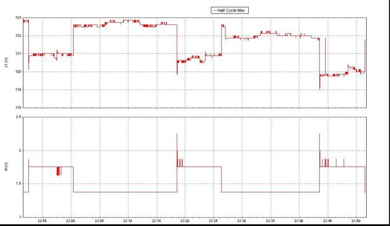
Today the voltage variation has been greater than before. The 1 minute average values have ranged from near 122.0 to 124.0 . The fluorescent lights flickered once today and I looked at the 1 second average plot and this corresponded to a 6 V momentary dip. It actually could have been greater but shorter than 1 second. We had a snow storm starting last night and there were 90,000 customers of DTE without power today. So it makes sense that voltage has been jumping around. I suppose that the variations I am seeing seem small to some in other parts of the country.

If I had a monitoring system at the shop, then I could correlate home data with shop data and from this separate system wide variations from local ones.

.
 
gar:

You are not making this easy are you?:D

How about something on the line? The pics you posted make it look like you have a lot of trees. Is the right-of-way trimmed clear? Is your secondary clear?

I guess with a storm you can't get reliable data at this point anyway.

I used to have a lot of blinks where I lived before. I had often thought of giving the EMC the business but just never got interested enough. I had battry back-ups on my PCs so the only real issue was my touch lamps cycling.
 
090406-2019 EST

miney:

There was no storm on Saturday. Just today. I am working on processing Saturday's data to try to get a good plot. This involves taking a string format like 4/4/2009 12:45:00 PM and converting it to numeric minutes. That's done. Also doing a running average over 10 seconds of the 1 second data to see if this helps viewing the data.

.
 
gar:

Here's a plot from a Fluke VR1710, Voltage Quality Recorder just showing L-G and N-G max voltage but it can show max, min and average all at the same time. I zoomed in on the plot a bit to show more detail, each division is five minutes, starting just before 11:00pm as you can see. It's on the circuit in my home back in January which has my furnace on it. The dips are my furnace cycling.


VR_1-1.jpg
 
090409-1051 EST

Bill:

Your plots are interesting. The neutral has about 1/4 the change of the hot side. Your on timing appears to be about 8 minutes on and 18 off, and it was probably cold at that time compared to now. Is your furnace forced hot air or hot water, and is it gas or geothermal?

My furnace is gas forced air and the blower time is very long compared to the burner time.

Where was the common terminal of the Fluke connected? I assume ground from your description, but physically where? Where was the neutral lead connected?

Just now I looked at my neutral at the main panel to the water pipe as it comes out of the floor. Total system load is about 2.75 KW. What is strange is this voltage is fluctuating from 4 to 15 MV at a rapid periodic rate of about 1 HZ. I do not think I have any load that would do that.

Do you know about how much current your furnace draws? And the wire size and length of your service wires from the transformer?

I get about 0.2 V change in voltage between hot and neutral from my 400 W furnace fan motor. My drop is almost all at the transformer. Another interesting point is that I can identify the turn on of the furnace blower from that of one of the refrigeration units by the longer inrush time resulting from the blower high inertia load. Also between my two furnaces there is a difference in the peak inrush.

Do you have a 1500 W electric heater to use as a test load and see what the voltage drops are for this magnitude of load change?

.
gar:

Forced air gas(installed in 1981). The furnace draws 3.65A while heating and the blower motor itself draws 3.2A. The blower comes ON first, less than a minute, than the burner, burner OFF and the blower runs till the heat drops to whatever point.

The VR1710 has a three prong plug and was plugged in a receptacle in a bedroom right above the furnace, might be the first one after the furnace. I'm unable to trace the wires as they ran some inside the duct work and I lose them!

I have a adapter that I can plug the VR1710 into that gives me three aligator clips to use anywhere.

The transformer is in my backyard about 50' to the house. It's #12 to the furnace.

Not sure if I have a 1500W heater, etc. for a load but the Ideal Suretest 61-165 showed at 15A, voltage drop to 112.7V for 7% at that receptacle. I have my whole house mapped out with it. The Suretest has a 12A setting which just showed the voltage drop to 116V for 6%.
 
Last edited:
090410-0757 EST

Bill:

Your furnace motor measurements indicate an approximate voltage change at the furnace of 1.75 - 0.4 = 1.35 V for a 3.65 A change. The 1.75 and 0.4 are my estimates from your plots. From these values the total source impedance from the furnace back into the pole transformer is 1.35/3.65 = 0.37 ohms.

From your Suretest I get the values:

15 A 7% 112.7
No load voltage = 112.7/0.93 = 121.2
Voltage change for 15 A = 121.2 - 112.7 = 8.5 V
Total source impedance = 8.5/15 = 0.57 ohms.

12 A 6% 116.0
No load voltage = 116.0/0.94 = 123.4
Voltage change for 12 A = 123.4 - 116.0 = 7.4 V
Total source impedance = 7.4/12 = 0.62 ohms.

If you put two duplex outlets at your main panel, one from one phase. and the second from the other phase, then you could look at the source impedance from the main panel into the pole transformer. These would be on separate breakers from anything else so that you actually viewed the bus voltages in the main panel.

Also useful for experiments would be a test lead from the ground rod at the pole transformer. This point would provide a measurement reference point very close to the center tap of the transformer. Then it would be possible to better estimate the impedances on the neutral and hot paths.

.
gar:

From my house map, the Suretest measures impedance also.

@15A
H-Z = 0.31 ohms
N-Z = 0.25 ohms

The total impedance is almost exactly what you calculated. I didn't record the 12A impedance at that time.

Wouldn't need any duplex as I have the Ideal adapter which gives you three color coded aligator clips.

I had mapped my garage too. I did some rewiring to correct some sloppy work and found some loose termination screws. Retested the circuit and it made hardly any difference in the impedance values!:rolleyes:
 
090410-1051 EST

Bill:

The reason I suggested the duplexes at the main panel is then anytime you want to do an experiment it is not necessary to remove the main panel cover.

If you make the voltage measurements at the main panel and produce a known current change somewhere, then you can determine the impedance from the main panel into the transformer. When applying the load it should be thru a different circuit and breaker than the one at the main panel where the voltage measurement is being made.

If you use the transformer ground rod as the voltage reference, then the neutral path impedance and the hot line impedance can be determined separately, at least to the extent that there is not much current flow on the pole ground rod.

Also if you measure the phase opposite the one being loaded and relative to the pole center tap (using the pole ground rod), then there should be little variation in the voltage of that opposite phase relative to the addition of the test load on the first phase.

.
 
Last edited:
090410-1051 EST

Bill:

The reason I suggested the duplexes at the main panel is then anytime you want to do an experiment it is not necessary to remove the main panel cover.

If you make the voltage measurements at the main panel and produce a known current change somewhere, then you can determine the impedance from the main panel into the transformer. When applying the load it should be thru a different circuit and breaker than the one at the main panel where the voltage measurement is being made.

If you use the transformer ground rod as the voltage reference, then the neutral path impedance and the hot line impedance can be determined separately, at least to the extent that there is not much current flow on the pole ground rod.

Also if you measure the phase opposite the one being loaded and relative to the pole center tap (using the pole ground rod), then there should be little variation in the voltage of that opposite phase relative to the addition of the test load on the first phase.

.
gar:

My main panel has been off for about two years as I'm always in there doing something!:rolleyes:
 
090410-1431 EST

Bill:

I had a thought that might be the case.

It is interesting that a machine repairman gets involved in these experiments and no electricians jumped in with their own measurements.

I had a classmate whose father as a young German immigrant was doing some filing one day in a plant when an older gentleman walk up to him and commented on his filing skill. Then the older person asked him why he was working here instead of over at the engineering labs. My classmate's father responded that he understood that you needed to know the correct person. The older gentleman, then responded --- now you do. Later my classmate's father became head of electrical engineering.

.
 
gar:

My main panel has been off for about two years as I'm always in there doing something!:rolleyes:

My panel cover was off, until I had kids. =) Now it goes back on, immediately.

Gar, haven't you heard the saying about the cobblers kids having no shoes? What would that say about the cobbler? :wink:

I plan to start up some monitoring soon enough... However, sadly, there are many irons in the fire currently. I hope to do some trending and simply dump all my data in a DB. Is anyone currently doing this on the cheap? I am comfortable doing this the expensive way, but discretionary spending had slowed to a trickle, and the hardware I currently have on hand would be clunky at best for this type of reading.

To add some irony to the bit. I am, by trade, an electrician and computer geek but, machining and wrench turning are my hobbys of mine. =)


Regards,

Doug S.
 
090410-2021 EST

Doug S.:

As a starting point the TED system is fairly useful. If you get their software, then data is collected into a data base file, and from within their TED Viewer you can export data to a comma delimited ASCII text file. Rather than putting the numeric data in the file comma delimited, they put double quotes around each of the numeric values making them into strings.

Bill worked in a plant where I had a number of gages. This is a large plant with lots of electricians, machine repairmen, pipe fitters, and bosses of various levels. It is possible that we worked together on some occasion, but I do not think so. Usually the helpers provided to me would only stick around until they could see a reason to disappear. There was little interest in learning about the whole machine. It is hard to troubleshoot a problem if you do not understand the whole machine. One day a pinion position machine had a lot of variability. It was a mechanical problem that resulted from an incorrect repair job. The machine repairmen I was assigned were willing to do what I asked of them, but they could care less about understanding why the problem occurred and how one could diagnose the problem. If Bill had been one of these people he would have hung around and been interested in learning all the details.

At a different company there was an electrician and machine repairman that were buddies and worked together doing each other's job when appropriate, this was a union shop as well as Bill's. When I was in this plant this pair always worked with me and made us an effective working group. From our close association they were able to solve many problems without my having to make a trip to the plant.

You need to know that my stuff was the electronic part of the machine, but 90% or more of the problems were mechanical or the parts being assembled. Even though the problems were mechanical I would be called in to solve the problems if troubleshooting the problem was not clear cut.

.
 
Even though the problems were mechanical I would be called in to solve the problems if troubleshooting the problem was not clear cut.

Isn't that standard? The thinking of "Hmm... we just tore up a drive shaft because a bearing failed but, the machine has a wire on it and has a computer hooked up to it" ... ... you know who get's called.

As far as TED goes. He seems interesting. It's NOT everything I'm after but it's 10? on the dollar.


Doug S.
 
Isn't that standard? The thinking of "Hmm... we just tore up a drive shaft because a bearing failed but, the machine has a wire on it and has a computer hooked up to it" ... ... you know who get's called.

What I've found is that the guy who has the record of figuring it out and getting it fixed is the one who gets called - regardless if the problem is actually part of his "job".
 
gar:

Back when I maintained a department, I always tried to work with or help other trades to fix a problem. I didn't do their jobs but have lent a hand in doing theirs. The machines were mechanical nightmares, so when there was a electrical problem, I was there to answer the famous question, what's it suppose to do now?

I had a good bunch of electricians to work with then but things have changed. Most often, they won't take the time to allow anybody to troubleshoot anything but when they pay a vendor like you to come in, they take the time!
 
090411-1036 EST

It is Saturday again, and my 1 V about 1/100 Hz square wave modulation of the supply voltage has reappeared. Quite similar to last Saturday, about 75 seconds on and 60 off for one sample period.

Someone is doing something specifically on Saturdays for some reason. I do not believe this occurred other days this last week. However, a much smaller and very much higher frequency event occurred during the week.

.

Grab your camera and take a drive around the hood.
 
Status
Not open for further replies.
Top