Waveform of a 750W Mercury Vapor Bulb

Status
Not open for further replies.

mbrooke

Batteries Included
Location
United States
Occupation
Technician
181102-1026 EDT

mbrooke:

Basics of what?

We have varying series current limiting resistance with time. Not shown. We have varying voltage across the bulb with time, neither averaged or instantaneous. Not shown. We have varying temperature in the bulb. Not shown, We have varying gas pressure in the bulb with time. Not shown. Etc.

.


Show- look at the meters. Voltage is close enough- it doesn't move beyond a few volts. However, starting current is higher and the bulbs glow brighter indicating a lower arc impedance when starting. Could the vid be better? Of course, but it the only one I know of on the net of someone ballasting an HID with an incandescent bulb.


How do the warm-up and hot-restrike times compare for the 120-volt vs. 240-volt bulbs?


Never compared run up, but hot re-strike is longer for 120 that I know of due to the switch having to cool down and re-close the filaments.
 

SG-1

Senior Member
181102-2019 EDT

SG-1:

The plots for the Hall probe show a small DC offset upward for the current measurement. The zero crossing shift might be removed if the current probe DC zero offset was removed.

It will be interesting to see the plots for the mercury vapor bulb using the hall probe. Also make a 10 turn coil thru the Hall probe which will make it a 20 A full scale probe.

.

Yes, the hall probe DC offset is all but impossible to remove. It was dialed in to slightly less than one amp, on the 100Amp scale. The 10 turn coil will help on a 100A scale.


Also completed the test with the shunt. I will make a separate post for that.
 

SG-1

Senior Member
750W Mercury Vapor Lamp Waveform Using Shunt Method

750W Mercury Vapor Lamp Waveform Using Shunt Method

As suggested 24ft of 16 gauge is being used in the place of an actual AC Shunt.

I will run the test again tomorrow using the hall effect probe & a 10 turn coil.
 

Attachments

  • 750WMercVaporLamp_V & C withShunt_24ft of16gauge.jpg
    750WMercVaporLamp_V & C withShunt_24ft of16gauge.jpg
    157.8 KB · Views: 0
  • 750WMerVaporLamp_ShuntMeasurement.jpg
    750WMerVaporLamp_ShuntMeasurement.jpg
    124.1 KB · Views: 0

gar

Senior Member
Location
Ann Arbor, Michigan
Occupation
EE
181102-2343 EDT

SG-1:

Your plot using the shunt now starts to make sense. The zero crossings for both voltage and current are almost coincident.

The positive slope zero crossings look very close, the negative not quite as close.

At 60 Hz there is some de-ionization taking place at low current, and that is why the delay in the buildup of current as the current grows after the zero crossing.

.
 

SG-1

Senior Member
750W Mercury Vapor Lamp Waveform Hall Efffect / i200s / Together / 10Turn Coil

750W Mercury Vapor Lamp Waveform Hall Efffect / i200s / Together / 10Turn Coil

Here is the waveform using the Hall Effect Amp Clamp Fluke 90i610 100A scale & a 10 turn coil, so divide amperes by 10.

Then The Fluke i200s 200A Scale & a 10 turn coil, so divide amperes by 10.

Then Both together

Test Setup

Tomorrow we follow the circuit path through the bulb with pictures.
 

Attachments

  • 750WMercVapor_A i200sAmpClamp&B Hall Effect AmpClamp.jpg
    750WMercVapor_A i200sAmpClamp&B Hall Effect AmpClamp.jpg
    141.7 KB · Views: 0
  • 750WMercVapor_HallSensorAmpClamp&10T Coil.jpg
    750WMercVapor_HallSensorAmpClamp&10T Coil.jpg
    155.4 KB · Views: 0
  • 750WMercVapor_i200s AmpClamp & 10T Coil.jpg
    750WMercVapor_i200s AmpClamp & 10T Coil.jpg
    155.2 KB · Views: 0
  • Dual AmpClamp & 10T Coil Setup_i200s&90i610.jpg
    Dual AmpClamp & 10T Coil Setup_i200s&90i610.jpg
    123.1 KB · Views: 0

gar

Senior Member
Location
Ann Arbor, Michigan
Occupation
EE
181103-0704 EDT

SG-1:

Your curves are looking very good.

When searching the Internet I have found it very difficult to find information on I-V curves for mercury vapor lamps, or even arc discharge.

One site, page 48,
http://thesesups.ups-tlse.fr/2573/1/2014TOU30242.pdf ,
in figure 1.4 shows a general plot. In the region "Non Thermal" you see the negative resistance portion of the arc discharge.

There are many variables that influence the V-I curve of a bulb.

Some other somewhat interesting links were:

https://www.google.com/search?ei=Mn...1j0i10j0i22i30j33i22i29i30j33i299.q7ESF3p04BY

https://en.wikipedia.org/wiki/Neon_lamp
Negative resistance between points A and B in the plot. You can make a simple oscillator with a battery, resistor, capacitor, and an NE-51 neon bulb.

.
 

mbrooke

Batteries Included
Location
United States
Occupation
Technician
Will mercury vapor lamps ever make a comeback? Thoughts? :?
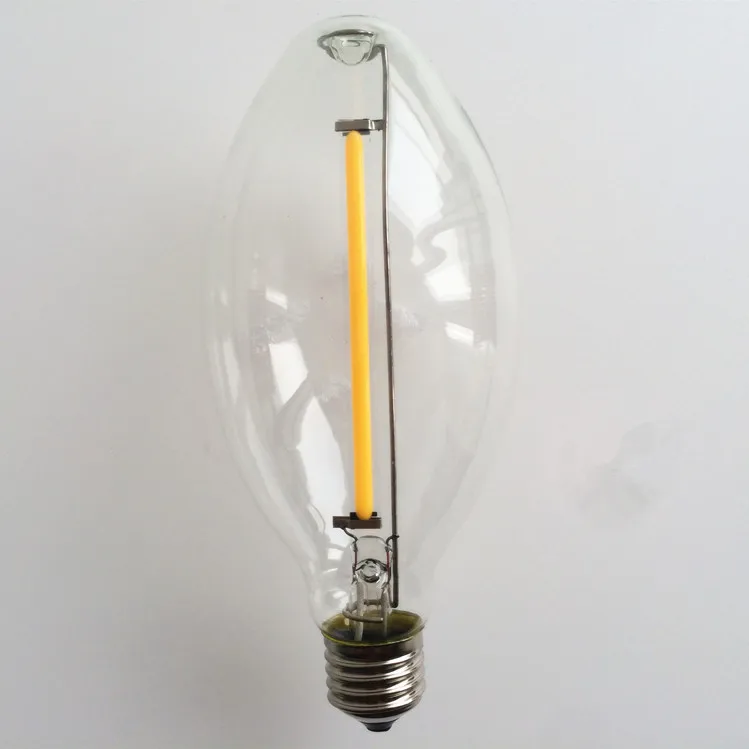

Probably not. LED lasts longer, way more lumens per what, instant restrike, mercury free and better color temperature and CRI. As is there soon going to have a LED filament substitute:


1X-E27-10w-led-filament-lamps-220v-Big-led-filament-bulb-led-bulb-ED80-Replace-Halogen.jpg
 

SG-1

Senior Member
750 Watt Mercury Vapor Self Ballast Lamp in Photos

750 Watt Mercury Vapor Self Ballast Lamp in Photos

Here is my best attempt to follow the circuit through the lamp in photos. The symmetry expected with the upper aux electrode is not there. We do not know the values of the carbon resistors or if they are the same. The lamp would have to be deconstructed to find that answer.
 

Attachments

  • PHOTO 1.jpg
    PHOTO 1.jpg
    125.2 KB · Views: 0
  • PHOTO 2.jpg
    PHOTO 2.jpg
    83.5 KB · Views: 0
  • PHOTO 3.jpg
    PHOTO 3.jpg
    123.9 KB · Views: 0
  • PHOTO 3A.jpg
    PHOTO 3A.jpg
    94.8 KB · Views: 0
  • PHOTO 4.jpg
    PHOTO 4.jpg
    68.8 KB · Views: 0
  • PHOTO 5.jpg
    PHOTO 5.jpg
    137.9 KB · Views: 0
  • PHOTO 6.jpg
    PHOTO 6.jpg
    67.3 KB · Views: 0
  • PHOTO 7.jpg
    PHOTO 7.jpg
    134.4 KB · Views: 0

SG-1

Senior Member
181103-0704 EDT

SG-1:

Your curves are looking very good.

When searching the Internet I have found it very difficult to find information on I-V curves for mercury vapor lamps, or even arc discharge.

One site, page 48,
http://thesesups.ups-tlse.fr/2573/1/2014TOU30242.pdf ,
in figure 1.4 shows a general plot. In the region "Non Thermal" you see the negative resistance portion of the arc discharge.

There are many variables that influence the V-I curve of a bulb.

Some other somewhat interesting links were:

https://www.google.com/search?ei=Mn...1j0i10j0i22i30j33i22i29i30j33i299.q7ESF3p04BY

https://en.wikipedia.org/wiki/Neon_lamp
Negative resistance between points A and B in the plot. You can make a simple oscillator with a battery, resistor, capacitor, and an NE-51 neon bulb.

.

With you guidance they now look good. I have learned a couple of things along the way about measurement & instruments of measurements. Thank You !!

The article for the neon bulb was the most interesting, who would have known the bulb could be used to determine if the signal was AC or DC & the polarity of the DC.
 

mbrooke

Batteries Included
Location
United States
Occupation
Technician
Here is my best attempt to follow the circuit through the lamp in photos. The symmetry expected with the upper aux electrode is not there. We do not know the values of the carbon resistors or if they are the same. The lamp would have to be deconstructed to find that answer.

Spectacular work- and much appreciated! :cool:


IMO a single prove MV would make it easier.
 

gar

Senior Member
Location
Ann Arbor, Michigan
Occupation
EE
181105-0746 EDT

SG-1:

The resistors are likely in the 10,000 to 100,000 ohm range. Physical size and full voltage that exists across arc element of the bulb. This is near full supply voltage to the entire bulb at initial start up minus something like the voltage drop across a neon bulb, about 60 V. After the mercury arc gets to full current, warmed up, then most of the arc voltage drop appears across the resistor.

In a 175 W mercury bulb I bought this weekend there is only one starter electrode. I haven't played with it yet, need a socket.

Spark and arc discharges have interested me for a long time, but I have not done much study on them.

In the mid 1950s I made a switch using three electrodes to control power to an automotive spark plug in a capacitor discharge system.

On board the USS Wisconsin in 1951 I had to troubleshoot the main battery fire control radar. It appeared to be an antenna problem. The antenna had four separate antennas. Transmitter power and received signal were connected to one antenna at a time thru a rotating switch driven from an 1800 RPM motor. Switch closure was via an arc initiated from the transmitter power.

To troubleshoot this I got a tall step ladder that allowed me to climb on top of the #2 16" gun turret. Took a scope, 1N34 diode up on top of the turret, and monitored the radar output. One antenna lobe was not putting out much power.

One of the other persons in our T-division took the rotary switch apart and found sea water in it. This antenna was mounted on top of the conning tower that was on top of the bridge. Earlier in the year we had been in a severe storm in the North Atlantic, 80 ft or more waves. The tops of these waves splashed over the conning tower, and this is probably how the water got inside the rotary switch.

.
 

SG-1

Senior Member
Spectacular work- and much appreciated! :cool:


IMO a single prove MV would make it easier.

Yes, a movie would have been nice. Nearly all my experience & equipment is with still photography. I was trying earlier this evening to record the wave form as it changes during start up. The voltage & current traces lay on top of each to begin with, in phase, then as the arc tube comes on line the wave form morphs into the pictures I posted. My little point & shoot camera can make videos, but it could not get a focus lock on the scope's screen. My SLR is too old to make a video. Have not given up yet...
 

mbrooke

Batteries Included
Location
United States
Occupation
Technician
Yes, a movie would have been nice. Nearly all my experience & equipment is with still photography. I was trying earlier this evening to record the wave form as it changes during start up. The voltage & current traces lay on top of each to begin with, in phase, then as the arc tube comes on line the wave form morphs into the pictures I posted. My little point & shoot camera can make videos, but it could not get a focus lock on the scope's screen. My SLR is too old to make a video. Have not given up yet...


Movie would have been to complex and made it more confusing IMHO. Still pictures break down a complex bulb into edible pieces. I would do the same with the oscillioscope, take pictures at various points and then compare them through time.
 

SG-1

Senior Member
181105-0746 EDT

SG-1:

The resistors are likely in the 10,000 to 100,000 ohm range. Physical size and full voltage that exists across arc element of the bulb. This is near full supply voltage to the entire bulb at initial start up minus something like the voltage drop across a neon bulb, about 60 V. After the mercury arc gets to full current, warmed up, then most of the arc voltage drop appears across the resistor.

In a 175 W mercury bulb I bought this weekend there is only one starter electrode. I haven't played with it yet, need a socket.

Spark and arc discharges have interested me for a long time, but I have not done much study on them.


.
That is why it does not matter that the upper carbon resistor is between the tungsten filaments, it is 10X or 100X greater in value than the filament.

Are you going to use a ballast with the 175 mercury bulb ?

I have a 100 watt mercury vapor bulb with one starter electrode also. Was thinking about using some tungsten lamps for ballast, but the operating voltage is not even listed in the bulb. It fits a standard 120 socket. Thinking it would be interesting to compare the waveforms in & out of the ballast. The outer shell of the 100W bulb is much thicker than the 750W bulb, it is thick like a halogen bulb.
 

gar

Senior Member
Location
Ann Arbor, Michigan
Occupation
EE
181107-1642 EST

SG-1:

Am I going to use a ballast with my 175 W bulb. Absolutely, one must use current limiting. What does ballast mean here? I am defining it as a current limiter. In particular I will use a relatively constant resistance, an Ohmite power resistor.

In my first preliminary experiments the resistance is about 58 ohms, and the supply is 124 V RMS, 175 V peak.

Breakdown is about 170 V to 150 V. First cycle always seems about 170 V, and more around 150 after that. Arc drop may be in the range of 15 to 25 V. There is oscillation in the arc current. The + and - arc voltages are somewhat different.

Looking at the bulb there is an orange glow close to each electrode, And a bluish glow between the orange glows. At present I am only leaving the bulb on for, at most, a few seconds.

It will be a while before I do more experiments.

.
 

SG-1

Senior Member
Sorry I was not clear. I was thinking about a standard ballast, for the 100W bulb it is an H38.

I too have seen the bluish glow. I turned off the 750W bulb & then turned it back on again. The electrodes were still orange, but cooling & the bluish glow was present at both electrodes. I did not wait for it to start again.
 
Status
Not open for further replies.
Top