Inverters typically have a 7 to 10 year lifespan so will have to be replaced at least once before the PV array is retired. Since it's getting harder, and maybe impossible in the future, to find an isolated string inverter non-isolated inverters will probably have to be used. How will grounded arrays be converted to ungrounded arrays if they are using USE-2 conductors? Just replace the inverter, keeping the USE-2 in the array, and running it ungrounded? Comb Ebay for NOS isolated inverters so the array can stay grounded? Convert to micro inverters? How do you see this going?
You are using an out of date browser. It may not display this or other websites correctly.
You should upgrade or use an alternative browser.
You should upgrade or use an alternative browser.
What is going to be the industry standard when replacing inverters?
- Thread starter pv_n00b
- Start date

- Status
- Not open for further replies.
jaggedben
Senior Member
- Location
- Northern California
- Occupation
- Solar and Energy Storage Installer
Well I think this is perhaps part of why the 2017 code is allowing USE-2 on ungrounded arrays again. So not to worry, I think.
I'm also inclined to regard it as a 'repair' that doesn't necessarily require using components that would have been code compliant when first installed but are now considered obsolete. Consider that a liberal interpretation of 90.4.
I think the real trick will be megger testing the wiring before installing a non-isolated inverter. My biggest worry would be the discovery of all the 600+ ohm tiny ground faults that never tripped the 1amp fuse in the old inverter but won't allow a new transformerless one to turn on. Don't want to discover that after promising the customer you have a solution, quoting the cost, and buying the new inverter. Do it first and then tell the customer if their array is fine or if it needs to be rewired and thus all options are on the table.
SolarPro
Senior Member
- Location
- Austin, TX
I'm also inclined to regard it as a 'repair' that doesn't necessarily require using components that would have been code compliant when first installed but are now considered obsolete. Consider that a liberal interpretation of 90.4.
That's my thought as well. You have an electrical system that met Code when it was installed. Some years later, that system requires O&M. The service technician pulls the broken part and inserts the part that will get the system up and running. If this is an HVAC system, no one cares is the replacement part is new and improved. But if it's a solar electric system, it becomes a big deal—even if the new part improves system safety. I don't get it, to be honest.
shortcircuit2
Senior Member
- Location
- South of Bawstin
According to a recent article I read, ungrounded arrays connected to a grounded system are really grounded, functionally grounded. I had always wondered how "Ungrounded PV Systems" were really ungrounded without "Galvanic Isolation". Seems like some of the PV codes are written to the benefit of the industry. Now the theory that I have been led to believe has shifted.
Carultch
Senior Member
- Location
- Massachusetts
According to a recent article I read, ungrounded arrays connected to a grounded system are really grounded, functionally grounded. I had always wondered how "Ungrounded PV Systems" were really ungrounded without "Galvanic Isolation". Seems like some of the PV codes are written to the benefit of the industry. Now the theory that I have been led to believe has shifted.
That is not what is meant by the new term "functionally grounded". Functionally grounded arrays are what was formerly known as grounded arrays, which tie a polarity to ground through a ground-fault fuse or breaker. The systems formerly known as "ungrounded" are now known as "non-isolated systems".
jaggedben
Senior Member
- Location
- Northern California
- Occupation
- Solar and Energy Storage Installer
That is not what is meant by the new term "functionally grounded". Functionally grounded arrays are what was formerly known as grounded arrays, which tie a polarity to ground through a ground-fault fuse or breaker. The systems formerly known as "ungrounded" are now known as "non-isolated systems".
I don't have the new code language in front of me but I believe you're incorrect on the meaning of the new term. A non-isolated DC system connected to a grounded AC system is considered functionally grounded according to the new definition. It is one type of functionally grounded system. The older arrays with a conductor grounded through a fuse are also considered functionally grounded. 99% of systems, old and new, will be considered functionally grounded under the new code. A truly ungrounded system under the new terms would probably be a low voltage one without an inverter.
Carultch
Senior Member
- Location
- Massachusetts
I don't have the new code language in front of me but I believe you're incorrect on the meaning of the new term. A non-isolated DC system connected to a grounded AC system is considered functionally grounded according to the new definition. It is one type of functionally grounded system. The older arrays with a conductor grounded through a fuse are also considered functionally grounded. 99% of systems, old and new, will be considered functionally grounded under the new code. A truly ungrounded system under the new terms would probably be a low voltage one without an inverter.
Functionally grounded means it "has an electrical reference to ground that is not solidly grounded". Systems grounded through a GFP device meet this definition.
Non-isolated DC systems connected to a grounded AC system are open to interpretation on whether or not this term applies. The DC side contains no reference to ground. It only contains a reference relative to the AC side, which itself is usually solidly or effectively grounded.
SolarPro
Senior Member
- Location
- Austin, TX
Functionally grounded means it "has an electrical reference to ground that is not solidly grounded". Systems grounded through a GFP device meet this definition.
Non-isolated DC systems connected to a grounded AC system are open to interpretation on whether or not this term applies. The DC side contains no reference to ground. It only contains a reference relative to the AC side, which itself is usually solidly or effectively grounded.
It's not really open for interpretation under NEC 2017. The Code-making panel deleted 690.35, "Ungrounded PV Systems," in its entirety. In effect, all PV systems, regardless of inverter topology, are functional grounded. There is no other classification.
Functional Grounded PV System. A PV system that has an electrical reference to ground that is not solidly grounded.
Informational Note: A functional grounded PV system is often connected to ground through a fuse, circuit breaker, resistance device, non-isolated grounded ac circuit, or electronic means that is part of a listed ground-fault protection system.
Carultch
Senior Member
- Location
- Massachusetts
It's not really open for interpretation under NEC 2017. The Code-making panel deleted 690.35, "Ungrounded PV Systems," in its entirety. In effect, all PV systems, regardless of inverter topology, are functional grounded. There is no other classification.
So what terminology distinguishes a GFP device grounded system, from a non-isolated system connected to a grounded AC grid?
jaggedben
Senior Member
- Location
- Northern California
- Occupation
- Solar and Energy Storage Installer
So what terminology distinguishes a GFP device grounded system, from a non-isolated system connected to a grounded AC grid?
None, from the point of view of 2017 code requirements. They are treated the same. The differences are entirely wrapped into the product standards, not the code.
jaggedben
Senior Member
- Location
- Northern California
- Occupation
- Solar and Energy Storage Installer
It's not really open for interpretation under NEC 2017. The Code-making panel deleted 690.35, "Ungrounded PV Systems," in its entirety. In effect, all PV systems, regardless of inverter topology, are functional grounded. There is no other classification.
Well, there's a classification for solidly grounded systems, too. But practically speaking, for most of us, you're right.
jaggedben
Senior Member
- Location
- Northern California
- Occupation
- Solar and Energy Storage Installer
...
Non-isolated DC systems connected to a grounded AC system are open to interpretation on whether or not this term applies. The DC side contains no reference to ground. It only contains a reference relative to the AC side, which itself is usually solidly or effectively grounded.
Strictly speaking, saying it's non-isolated means there's no difference between the DC and AC side references. I suppose one could argue that, to be crystal clear, the definition for functionally grounded should include the phrase 'when operating'.
shortcircuit2
Senior Member
- Location
- South of Bawstin
Consult The AHJ
Consult The AHJ
Until your under the 2017 Code, you had better consult the AHJ as to whether he/she will allow the change from transformer based inverters to transformerless inverters under 90.4, with special permission that is usually granted in writing. There may be issues for some AHJ's with leaving all that USE-2 in the ARRAY and most early PV modules didn't have PV wire whips either.
Under the 2014 Code...
Under the 2017 Code...
That's my short lists on the subject.
Should we add RAPID SHUTDOWN to those lists...")
Consult The AHJ
Inverters typically have a 7 to 10 year lifespan so will have to be replaced at least once before the PV array is retired. Since it's getting harder, and maybe impossible in the future, to find an isolated string inverter non-isolated inverters will probably have to be used. How will grounded arrays be converted to ungrounded arrays if they are using USE-2 conductors? Just replace the inverter, keeping the USE-2 in the array, and running it ungrounded? Comb Ebay for NOS isolated inverters so the array can stay grounded? Convert to micro inverters? How do you see this going?
Until your under the 2017 Code, you had better consult the AHJ as to whether he/she will allow the change from transformer based inverters to transformerless inverters under 90.4, with special permission that is usually granted in writing. There may be issues for some AHJ's with leaving all that USE-2 in the ARRAY and most early PV modules didn't have PV wire whips either.
Under the 2014 Code...
- Ask for 90.4 special permission.
- There may be issues with other than type PV wire as exposed single conductor cable.
- Change DC disconnects to open both poles of the circuit.
- Change fused combiners to protect both poles of the DC circuit. Comply with 690.15(C) disconnect rule.
- The inverter must comply with 690.11
- Re-identify all white markings on DC field wiring.
- Warning labels should be applied. 690.35(F)
Under the 2017 Code...
- There may be issues with other than USE-2 or PV wire as exposed single conductor cable. Request special permission under 90.4 if necessary.
- Change DC disconnects to open both poles of the circuit.
- The inverter must comply with 690.11
- Locate disconnects within 10ft of inverters. Within 10ft of combiners (>30-amp output) 690.15(A)
- Re-identify all white markings on field wiring.
- Warning labels should be applied.
That's my short lists on the subject.
Should we add RAPID SHUTDOWN to those lists...
Carultch
Senior Member
- Location
- Massachusetts
Until your under the 2017 Code, you had better consult the AHJ as to whether he/she will allow the change from transformer based inverters to transformerless inverters under 90.4, with special permission that is usually granted in writing. There may be issues for some AHJ's with leaving all that USE-2 in the ARRAY and most early PV modules didn't have PV wire whips either.
Under the 2014 Code...
- Ask for 90.4 special permission.
- There may be issues with other than type PV wire as exposed single conductor cable.
- Change DC disconnects to open both poles of the circuit.
- Change fused combiners to protect both poles of the DC circuit. Comply with 690.15(C) disconnect rule.
- The inverter must comply with 690.11
- Re-identify all white markings on DC field wiring.
- Warning labels should be applied. 690.35(F)
Under the 2017 Code...
- There may be issues with other than USE-2 or PV wire as exposed single conductor cable. Request special permission under 90.4 if necessary.
- Change DC disconnects to open both poles of the circuit.
- The inverter must comply with 690.11
- Locate disconnects within 10ft of inverters. Within 10ft of combiners (>30-amp output) 690.15(A)
- Re-identify all white markings on field wiring.
- Warning labels should be applied.
That's my short lists on the subject.
Should we add RAPID SHUTDOWN to those lists...
I would think that in general, repairs of a system can remain in compliance with the codes they were once compliant with. So if you are replacing an inverter, or replacing a failed racking structure, you wouldn't necessarily need to add rapid shutdown or AFCI to a system that was built in 2008. You would just need to bring it up to the way it should be in 2008. You would fix the issue and correct any existing violations that slipped through the cracks. It is an AHJ specific call, but in Massachusetts we have Rule 3 which actually puts this in writing.
jaggedben
Senior Member
- Location
- Northern California
- Occupation
- Solar and Energy Storage Installer
...
Under the 2017 Code...
- There may be issues with other than USE-2 or PV wire as exposed single conductor cable. Request special permission under 90.4 if necessary.
- Change DC disconnects to open both poles of the circuit.
- The inverter must comply with 690.11
- Locate disconnects within 10ft of inverters. Within 10ft of combiners (>30-amp output) 690.15(A)
- Re-identify all white markings on field wiring.
- Warning labels should be applied.
That's my short lists on the subject.
Should we add RAPID SHUTDOWN to those lists...
Not sure the red part is correct for the 2017 code. But I keep posting when I'm at work and the book is at home.
Carultch
Senior Member
- Location
- Massachusetts
Not sure the red part is correct for the 2017 code. But I keep posting when I'm at work and the book is at home.
It is. As a matter of fact, even systems formerly known as grounded systems, will now require it.
SolarPro
Senior Member
- Location
- Austin, TX
SolarPro
Senior Member
- Location
- Austin, TX
Basically, once you do away with the myth of the solidly grounded PV system, you can open both poles of a PV circuit without violating any rules about not opening an intentionally grounded conductor. Opening both poles of the PV power circuits improves safety for O&M technicians, especially those chasing ground faults.
Source: NEC 2017 Updates for PV Systems
FUNCTIONAL GROUNDING
Article 100 of the NEC defines solidly grounded as “connected to ground without inserting any resistor or impedance device.” Solidly grounded ac electrical systems are the most common way to supply power to loads in the US. When PV systems were new to the NEC, it was important that we design them in a similar fashion, with a solidly grounded system conductor, as doing so increased AHJ acceptance.
As the number of fielded PV systems grew, industry stakeholders realized the importance of dc ground-fault protection. The NEC first codified requirements for dc ground-fault protection in the 1990s; subsequent revision cycles extended these requirements to cover virtually all PV systems. Early dc ground-fault protection systems used an overcurrent-protection device in the grounded conductor-to-ground bond. The implementation of this simple design effectively replaced solidly grounded PV systems with not so solidly grounded PV systems. However, everyone continued to refer to these as grounded PV systems, out of fear that AHJs would otherwise cry foul.
NEC 2017 frees us from this confusion by introducing a new definition under 690.2. It defines a functional grounded PV system as one “that has an electrical reference to ground that is not solidly grounded.” This definition adopts terminology commonly used in Europe to describe how PV systems are referenced to ground in practice. An informational note further clarifies: “A functional grounded PV system is often connected to ground through a fuse, circuit breaker, resistance device, non-isolated grounded ac circuit, or electronic means that is part of a listed ground-fault protection system. Conductors in these systems that are normally at ground potential may have voltage to ground during fault conditions.” In other words, virtually all of the PV systems installed over the last two decades are functional grounded rather than solidly grounded systems.
Design implications. This simple change in our understanding of PV system grounding has profound design implications. Not only does it impact where you place disconnects and overcurrent protection in PV circuits, but it also allows for a unified approach to these parameters. As long as we treated one subset of PV systems as solidly grounded and another subset as ungrounded, for example, you needed to have two sets of design standards.
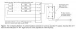
By acknowledging that all modern PV systems are not solidly grounded (ungrounded or functional grounded), CMP 4 was able to eliminate 690.35, “Ungrounded PV Systems,” in its entirety. We then defined a single set of design standards, shown schematically in Figure 3, that apply to the dc side of a functional grounded PV system:
+ Overcurrent protection is required in only one leg of a PV circuit [690.9(C)]
+ Disconnecting means are required in both legs of a PV circuit [690.15]
+ USE-2 or PV Wire is allowed as single-conductor cable in a PV array [690.31(C)]
These unified design standards solve a number of problems for installers and inspectors. As long as we treated some PV systems as solidly grounded, for example, opening the “grounded” conductor created the appearance of a Code violation in the minds of many AHJs and inspectors due to requirements in Article 240. However, if a ground fault occurs in a fuse-grounded PV system and the “grounded” conductor is bolted rather than switched, the only safe way for a field technician to service the system is to work at night. The CMP addressed this issue in NEC 2014 by creating an exception to 690.17(D) that allowed a disconnect switch for opening an accessible grounded conductor. Only qualified persons could access the switch, which was dedicated to PV array maintenance only. In NEC 2017, the revised language in 690.15 eliminates all of this confusion. It not only improves safety in the field but also eliminates the need for at least three previously required warning signs, including 690.5(C), 690.7(E) and 690.35(F).
The replacement of legacy grounded inverters with new and improved transformerless inverters is an important pain point that NEC 2017 addresses. Though legacy grounded inverters are susceptible to blind spots in ground-fault detection, earlier Code cycles held these systems to less-restrictive wiring method requirements than “ungrounded” systems with transformerless inverters, even though the latter offer improved ground-fault protection. Both USE-2 and PV Wire were Code-compliant single-conductor wiring methods for grounded inverters, whereas only PV Wire was compliant with transformerless inverters. The unified design standards in NEC 2017 eliminate this distinction and allow installers to replace grounded inverters with transformerless inverters without having to upgrade single-conductor wiring. To bring a legacy system into compliance with NEC 2017, installers need only rewire or replace the dc disconnects.
Source: NEC 2017 Updates for PV Systems
I would think that in general, repairs of a system can remain in compliance with the codes they were once compliant with. So if you are replacing an inverter, or replacing a failed racking structure, you wouldn't necessarily need to add rapid shutdown or AFCI to a system that was built in 2008. You would just need to bring it up to the way it should be in 2008. You would fix the issue and correct any existing violations that slipped through the cracks. It is an AHJ specific call, but in Massachusetts we have Rule 3 which actually puts this in writing.
It depends on the AHJ. If the AHJ feels that the repair touches enough of the system as a whole, or is a major change to the functionality, they can have you bring the whole system up to current code. Changing from an isolated to non-isolated inverter will probably result in the more knowledgable AHJs looking at the whole system for upgrade.
Grounding, solid, functional, impedance
Grounding, solid, functional, impedance
The NEC overall only recognizes 3 kinds of grounding, solidly grounded, ungrounded, and impedance grounded.
Solid grounded is when you have a solid conductor connecting the grounded conductor to ground, pretty simple.
Ungrounded is when there is nothing connecting the grounded conductor to ground. Used where grounding is not required or where grounding would result in the shutdown of industrial processes that require orderly shutdown.
Impedance grounding is anything that replaces the solid conductor connecting the grounded conductor to ground with an impedance to limit ground fault current. Usually used in industrial applications where a ground fault will not require the system to be immediately shut down but will provide immediate indication of a fault.
Functional grounded in 690 is not a form of grounding as defined in the rest of the NEC. Think of it more as an ungrounded system that has sensors that can detect when a ground fault happens and a fault will result in shutting down the inverter and require someone to come out and fix the fault to get the system up again.
In the past this sensor has been the GFDI system where a fuse connected between one conductor and ground was used to detect a ground fault, shutdown the inverter, and leave the array ungrounded. We were really fooling ourselves in calling these systems solidly grounded since the "solid ground" went away then there was a ground fault large enough to blow the fuse. No other solidly grounded system in the NEC worked like that. We did it to calm down everyone who felt that an ungrounded PV system was too unfamiliar and possibly dangerous to have on residential roofs. Remember that outside of a limited number of industrial installations, which 99.9% of residential AHJs have no experience with, there are few non-utility owned ungrounded electrical systems in the US and no residential systems are ungrounded. We like solidly grounded systems here and there is a comfort that has built up around that. We were also asking to put 600V on a residential roof which people were balking at. Asking for 600V and ungrounded at the same time was not going to work. So compromises were made.
Calling PV arrays Functional Grounded is really just another way of implying that the array is grounded when it is not to make people feel better. I think it is progress because at least we are not saying these are solidly grounded when they never were, which was dangerous to people working on these systems when they were faulted. But if you treat these like the ungrounded systems they really are everything will be fine.
That's my breakdown of PV system grounding.
One last thing, isolated vs. non-isolated does not tell you what system grounding will be allowed. You just can't have grounding on both sides of the non-isolated inverter due to the possibility of current loops forming and providing alternate ground return paths.
Grounding options by inverter type.
Non-Isolated Inverters:
Isolated Inverters:
By design since we usually have a grounded AC system we are interconnection to it requires that non-isolated inverters be ungrounded on the DC side but that is due to the application and not the type of inverter.
Grounding, solid, functional, impedance
The NEC overall only recognizes 3 kinds of grounding, solidly grounded, ungrounded, and impedance grounded.
Solid grounded is when you have a solid conductor connecting the grounded conductor to ground, pretty simple.
Ungrounded is when there is nothing connecting the grounded conductor to ground. Used where grounding is not required or where grounding would result in the shutdown of industrial processes that require orderly shutdown.
Impedance grounding is anything that replaces the solid conductor connecting the grounded conductor to ground with an impedance to limit ground fault current. Usually used in industrial applications where a ground fault will not require the system to be immediately shut down but will provide immediate indication of a fault.
Functional grounded in 690 is not a form of grounding as defined in the rest of the NEC. Think of it more as an ungrounded system that has sensors that can detect when a ground fault happens and a fault will result in shutting down the inverter and require someone to come out and fix the fault to get the system up again.
In the past this sensor has been the GFDI system where a fuse connected between one conductor and ground was used to detect a ground fault, shutdown the inverter, and leave the array ungrounded. We were really fooling ourselves in calling these systems solidly grounded since the "solid ground" went away then there was a ground fault large enough to blow the fuse. No other solidly grounded system in the NEC worked like that. We did it to calm down everyone who felt that an ungrounded PV system was too unfamiliar and possibly dangerous to have on residential roofs. Remember that outside of a limited number of industrial installations, which 99.9% of residential AHJs have no experience with, there are few non-utility owned ungrounded electrical systems in the US and no residential systems are ungrounded. We like solidly grounded systems here and there is a comfort that has built up around that. We were also asking to put 600V on a residential roof which people were balking at. Asking for 600V and ungrounded at the same time was not going to work. So compromises were made.
Calling PV arrays Functional Grounded is really just another way of implying that the array is grounded when it is not to make people feel better. I think it is progress because at least we are not saying these are solidly grounded when they never were, which was dangerous to people working on these systems when they were faulted. But if you treat these like the ungrounded systems they really are everything will be fine.
That's my breakdown of PV system grounding.
One last thing, isolated vs. non-isolated does not tell you what system grounding will be allowed. You just can't have grounding on both sides of the non-isolated inverter due to the possibility of current loops forming and providing alternate ground return paths.
Grounding options by inverter type.
Non-Isolated Inverters:
- Grounding on the DC side and none on the AC side
- Grounding on the AC side and none on the DC side
- Grounding on neither side
Isolated Inverters:
- Grounding on the DC side and none on the AC side
- Grounding on the AC side and none on the DC side
- Grounding on the AC and DC side
- Grounding on neither side
By design since we usually have a grounded AC system we are interconnection to it requires that non-isolated inverters be ungrounded on the DC side but that is due to the application and not the type of inverter.
- Status
- Not open for further replies.