Looking at a detail for ?stacking? transformers in an electrical closet it indicates a transformer and a uni-strut rack constructed around it followed by a xfmr mounted above the first with adequate clearances for air movement, the question is it indicates vibration isolators on the floor below xfmr.1 and on the uni-strut rack below xfmr.2 if transformers already come with isolators internal to the equipment would not the additional isolators possibly create more problems within the equipment?
You are using an out of date browser. It may not display this or other websites correctly.
You should upgrade or use an alternative browser.
You should upgrade or use an alternative browser.
xfmr mounting
- Thread starter Mike01
- Start date
- Status
- Not open for further replies.
petersonra
Senior Member
- Location
- Northern illinois
- Occupation
- Semi-retired engineer
Its possible whoever designed the thing already took that into account.
The guy that designed the rack is the person to ask.
The guy that designed the rack is the person to ask.
- Location
- Illinois
- Occupation
- retired electrician
I don't see how the additional isolators would cause a problem. I would be concerned about the heat from the lower one going right up into the upper one and cooking it.
What you must consider is a 30degC avg ambient w/ a 40degC ambient maximim.
If the lower transformer doesn't cause the one above to exceed it then is is a non issue.
This woulld be based upon class H (220degC) insulation class, 150deg rise, 40degC ambient with a 30degC winding hot spot allowance.
40+150+30=220. If you increase the 40degC at full load you will exceed the insulation rating decreasing the life of the transformer.
So no matter where the transformer is located, such as above another transformer, as long as it is in a location that is 40degC ambient or less there should be no problem.
Steve G
Member
- Location
- Atlanta, GA
templdl... where was this info gathered from?
- Location
- Massachusetts
don_resqcapt19 said:I would be concerned about the heat from the lower one going right up into the upper one and cooking it.
Having to stack transformers is becoming very common in a lot of office buildings.
It may not be the best idea to do so but the size of the electric rooms requires it.

Pierre C Belarge
Senior Member
- Location
- Westchester County, New York
As Bob mentioned (late last night or early this morning-take your pick), The electric closets have become smaller and smaller, and the loads in the building larger and larger....so they stack the Transformers.
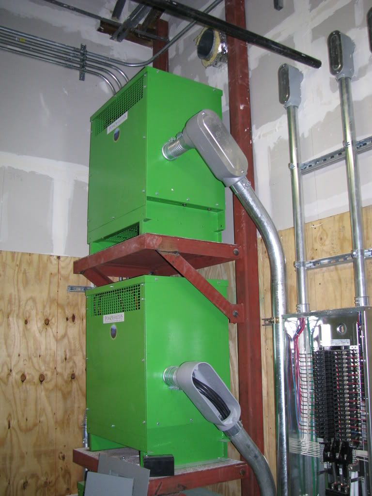
Both of these installs are 3 high.
Both of these installs are 3 high.
- Location
- Illinois
- Occupation
- retired electrician
If they are sized by Article 220 calculations, then it probably is not an issue, but I have replaced more than on in industrial occupancies where the upper one was cooked as a direct result of excessive heat from the lower one.iwire said:Having to stack transformers is becoming very common in a lot of office buildings.
It may not be the best idea to do so but the size of the electric rooms requires it.
masterinbama
Senior Member
- Location
- Huntsville Alabama
you are so right about electrical rooms getting smaller and smaller.Had one last year that was only 8' x 12' see if you can cram it all in there was all I was told. Here is the equipment list 1-800 amp I-line, 1-1000 amp I-line EM panel, 1-1000 amp transfer switch, 1-200 amp 277/480 panel, 1-200 amp 120/208 general use panel,1-100 amp EM lighting panel, 1-100 amp 120/208 EM panel, 1-75 KVA and 1- 30 KVA transformer. All in grs conduit I have some pics will post when I find them.
electroman00
Member
- Location
- Orlando FL
I sure would like to have the inspector who inspected those xformers on all my jobs.
If he passed that xformer installation, lord knows what he'll pass.
Both those xformer installations are code violations.
They wouldn't fly here in Orlando FL. for sure.
Stacking them isn't the problem.
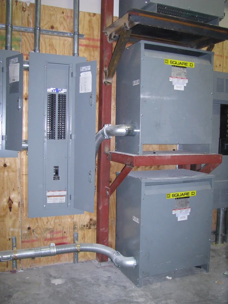
Clearance from the wall is, MFG spec's for those xformers require 6" especially the front and back where the vents are.
I also would have a talk with the person who used the LB's in the top photo.
That's 100+ bucks added to the job for no good reason. Flex 90's work just fine, as in the bottom photo at 40% of the cost of LB's
The open panel in the top pic is real nice except 50% of the contractors I've worked for would not be impressed.
1 Wires to breakers cut short.
2 Tie wraps in panel bundling wires (not required).
3 1st strut above panel not required (adds to cost)
You can purchase 2" X 2" isolation pads for the xformer which I always use, they help reduce noise and isolate from concrete.
Xformers don't seem to be bolted in place (violation).
And it looks like the xformer isolation bolts on the SquareD xformer has the bolts removed, can't really see.
And I would be concerned about the vent pipe above the xformer, depending on what it's for, it may be a violation.
And two grounding conductors in one (one hole) lug in panel.
Most obvious is no FRC on penetrations, might be premature pic's.
Bottom line is the inspectors here would fail it for the clearance issue.
Other then that it looks pretty.
Have a good day all.....
If he passed that xformer installation, lord knows what he'll pass.
Both those xformer installations are code violations.
They wouldn't fly here in Orlando FL. for sure.
Stacking them isn't the problem.
Clearance from the wall is, MFG spec's for those xformers require 6" especially the front and back where the vents are.
I also would have a talk with the person who used the LB's in the top photo.
That's 100+ bucks added to the job for no good reason. Flex 90's work just fine, as in the bottom photo at 40% of the cost of LB's
The open panel in the top pic is real nice except 50% of the contractors I've worked for would not be impressed.
1 Wires to breakers cut short.
2 Tie wraps in panel bundling wires (not required).
3 1st strut above panel not required (adds to cost)
You can purchase 2" X 2" isolation pads for the xformer which I always use, they help reduce noise and isolate from concrete.
Xformers don't seem to be bolted in place (violation).
And it looks like the xformer isolation bolts on the SquareD xformer has the bolts removed, can't really see.
And I would be concerned about the vent pipe above the xformer, depending on what it's for, it may be a violation.
And two grounding conductors in one (one hole) lug in panel.
Most obvious is no FRC on penetrations, might be premature pic's.
Bottom line is the inspectors here would fail it for the clearance issue.
Other then that it looks pretty.
Have a good day all.....
- Location
- Massachusetts
electroman00 said:1 Wires to breakers cut short.
They seem to reach the terminals, and it looks real good to me.
2 Tie wraps in panel bundling wires (not required).
Not a violation
3 1st strut above panel not required (adds to cost)
Yeah $3.00 in strut is a real killer. :smile:
And two grounding conductors in one (one hole) lug in panel.
You must mean the grounded conductors?
I will be willing to bet that Sq D lug is listed for two conductors.
macmikeman
Senior Member
- Location
- Planet macmikeman
The thing I noticed when looking at the pictures was the green colored tranny's, and the entry points for the conduits and wire. First question is am I looking at some sort of new "green" technology transformer, maybe energy saving?? Second thing is most of the trannys I ever hooked up had a line on the interior that stated that no penetrations were to be made above the line. I wonder if the ones in the picture have that restriction as well.
HighWirey
Senior Member
- Location
- Cocoa, Florida, USA
You state that you are "Looking at a detail for ?stacking? transformers".
Did you design that detail, or are you just going to bid the project?
Bid what you see on the print. It is laudible that you are looking for possible problems prior to the bid, however we ECs only get paid to install the stuff that is on that print.
The time to straighten out anomolies is after you have a contract, then it returns your time, plus.
BTW, I have followed up on and installed many new 'stacked' transformer arrangements in telephone booth sized equipment closets at the Kennedy Space Center, FL. No ventilation, and hotter-n-hades in those closets, and those transformers, like those Timex's, took a likkin, and keep'd on ticken'. Most of them (circa 1964) are still ticken'.
Work'in For That Free Tee . . .
petersonra
Senior Member
- Location
- Northern illinois
- Occupation
- Semi-retired engineer
transformers can be pretty tough birds. it takes a lot to kill a good one.
in most cases if there is even a little ventialtion into a room, the transformers will cool enough to survive.
most of the heat from the transformers tends to come out through the grills on the front or sides. that tends to direct the heat away from the transformers above it. I can't recall ever seeing one with grills on top.
HighWirey
Senior Member
- Location
- Cocoa, Florida, USA
Man, you sure are a 'tough marker'.
Orlando inspections must have tightened up since I left 30 years ago.
You won't give the guy four ty-raps, yet you purchase and install iso pads for your transformers?
I'll give you the clearance issue on those SqDs, and have never seen a 'greenie'. Maybe they allow the zero clearance to the rear. And the penetrations, don't know about that on a 'greenie'.
Been out of the loop for a while, but cast aluminium LBs $100 more than steel flex 90's?
50% of your former employers must have those 'bottom feeders' that we 'fair bidding' central Florda ECs know and love.
Your quote "Other then that it looks pretty".
Engineers have a saying "Form Follows Function". But, you know, Form does have a place in that equation.
Best Wishes Everyone
HighWirey
Senior Member
- Location
- Cocoa, Florida, USA
Pierre,
Again thank you for the nice, clear pictures.
You have mastered the concept that 'light is our friend'. As electricians, we should know that, however some brothers are still in the dark . . .
Best Wishes Everyone
Again thank you for the nice, clear pictures.
You have mastered the concept that 'light is our friend'. As electricians, we should know that, however some brothers are still in the dark . . .
Best Wishes Everyone
Pierre C Belarge
Senior Member
- Location
- Westchester County, New York
Adding to Bob's post.
The green transformers are fairly new around by us...they are energy efficient units. I have other pictures of them showing the labels.
I also have a question as to the entry point, I will let you know when they open one for me.
The spacing from the wall meets the minimum distance required, it may be hard to see in the photo. Remember, the metal supports behind the transformers are 4 inch and the transformers sit another 2 inches in front of the supports.
The lug for the double neutral is listed for the install.
The conductors to the CBers are far from being too short.
"The open panel in the top pic is real nice except 50% of the contractors I've worked for would not be impressed"
I am not too sure if they were trying to impress you. :wink:
Take a closer look, all of the transformers are bolted in place.
Fire caulking is being installed by the GC, not our issue.
The vent pipe has to be changed...there were only supposed to be 2 units stacked. The design was changed much later in the install process.
"Other then that it looks pretty"
I would really hate to see when you have something to complain about. :grin:
I give the guys on this job a lot of credit. Changes galore, no time to install the changes and the new tenant of the building (the County) breathing down their backs. Engineers, designers throwing changes at them, even as I was inspecting.
As much as I have to take a close look, I still understand and remember what it is like to work in those types of environments.
And the rooms were packed...making it work is sometimes an artform.
The green transformers are fairly new around by us...they are energy efficient units. I have other pictures of them
showing the labels.I also have a question as to the entry point, I will let you know when they open one for me.
The spacing from the wall meets the minimum distance required, it may be hard to see in the photo. Remember, the metal supports behind the transformers are 4 inch and the transformers sit another 2 inches in front of the supports.
The lug for the double neutral is listed for the install.
The conductors to the CBers are far from being too short.
"The open panel in the top pic is real nice except 50% of the contractors I've worked for would not be impressed"
I am not too sure if they were trying to impress you. :wink:
Take a closer look, all of the transformers are bolted in place.
Fire caulking is being installed by the GC, not our issue.
The vent pipe has to be changed...there were only supposed to be 2 units stacked. The design was changed much later in the install process.
"Other then that it looks pretty"
I would really hate to see when you have something to complain about. :grin:
I give the guys on this job a lot of credit. Changes galore, no time to install the changes and the new tenant of the building (the County) breathing down their backs. Engineers, designers throwing changes at them, even as I was inspecting.
As much as I have to take a close look, I still understand and remember what it is like to work in those types of environments.
And the rooms were packed...making it work is sometimes an artform.
masterinbama
Senior Member
- Location
- Huntsville Alabama
how can everyone here overlook the # of wires in the 2 2" conduits leaving the panel in one of the pics.Are they over sized for derating. I count 21 + 7 neutrals and a egc what say yooz guyz
masterinbama said:how can everyone here overlook the # of wires in the 2 2" conduits leaving the panel in one of the pics.Are they over sized for derating. I count 21 + 7 neutrals and a egc what say yooz guyz
Looks like #12, could be 10's I suppose.
20A cb's or 15's?
No obvious violation, I'm sure Pierre wouldn't miss that.
- Location
- Massachusetts
masterinbama said:how can everyone here overlook the # of wires in the 2 2" conduits leaving the panel in one of the pics.Are they over sized for derating. I count 21 + 7 neutrals and a egc what say yooz guyz
I say good eye.
I bet they are # 10s and that would be 21 current carrying conductors.
Under the NEC and those conditions the 10s would only be rated 18 amps so you would need to use 15 amp breakers
Here in MA that would be legal, we have less restrictive derating rules.
- Status
- Not open for further replies.