electrofelon
Senior Member
- Location
- Cherry Valley NY, Seattle, WA
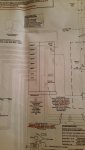
Used to create artificial neutral, mitigate harmonics, & more. Check it out on Wikipedia:What is the purpose of the ziz zag transformer in this drawing?
The customer transformer is a grounded wye-grounded wye transformer, so I do not see any need for a grounding transformer.
The only thing I can think of is that someone has specified that the inverter output has to remain solidly grounded even when the disconnect is open.

I was thinking (mistakenly) of the disconnect also opening the neutral.I can't see how an open disconnect would unground the inverter output.
There is no neutral conductor running to it on the drawing though, just indicates a ground connection at the midpoint.Used to create artificial neutral, mitigate harmonics, & more. Check it out on Wikipedia:
https://en.wikipedia.org/wiki/Zigzag_transformer
There is no neutral conductor running to it on the drawing though, just indicates a ground connection at the midpoint.
Yet the source ahead of this appears to already be a grounded wye, which should already fulfill that purpose.To me, it looks like the midpoint is the artificial neutral, and the only purpose of it is to provide a balanced connection to the earth.
Looking hard at the drawing, I renew my comment that the source grounding is only seen when the disconnect is closed, since there is no neutral connection to the inverters. I do not see why floating the inverter output (when not operating, because of anti-islanding) should be harmful, but it still might be the motivation.Yet the source ahead of this appears to already be a grounded wye, which should already fulfill that purpose.
Looking hard at the drawing, I renew my comment that the source grounding is only seen when the disconnect is closed, since there is no neutral connection to the inverters. I do not see why floating the inverter output (when not operating, because of anti-islanding) should be harmful, but it still might be the motivation.
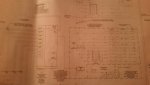
Also notice the cutting off. It looks like the breaker is a normally open breaker that closes upon activation of the "S" on the right side of the page. Perhaps seeing the rest of the drawing would give some clue as to the intention. I don find it interesting that this is odd enough that no one here with the vast knowledge represented, has yet said, "Oh that is a ..."
"Direct trip. If 480V 1200A circuit breaker is open, trip sent to 13.2KV 1200A VCB."
Looking hard at the drawing, I renew my comment that the source grounding is only seen when the disconnect is closed, since there is no neutral connection to the inverters. I do not see why floating the inverter output (when not operating, because of anti-islanding) should be harmful, but it still might be the motivation.
Sent from my XT1585 using Tapatalk
Here is what the note 11 says:
"Direct trip. If 480V 1200A circuit breaker is open, trip sent to 13.2KV 1200A VCB."
1200A at 13.2KV ??? That can't be right.
(Is this when an RFI becomes a WTF?)