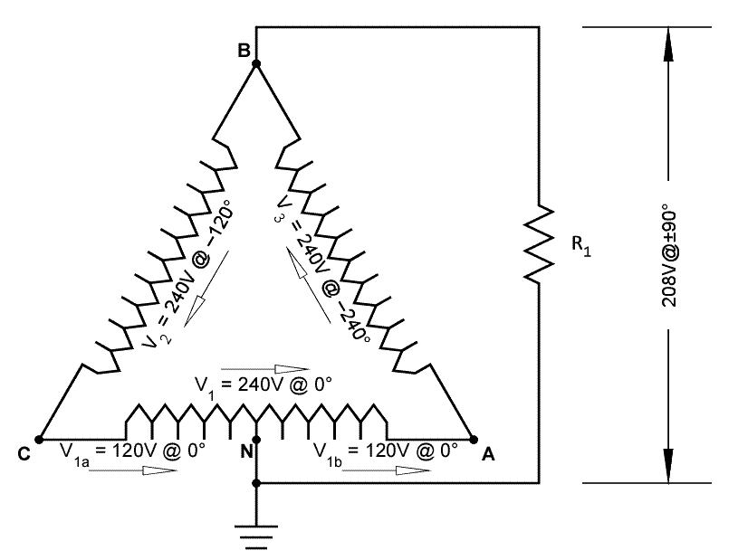
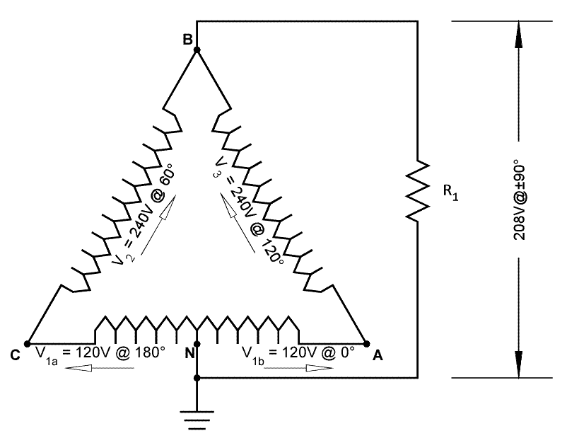
3 phase Delta High Leg Single Phase Load

Status
Not open for further replies.

lefty

Member
Location
Oklahoma
Seen this a lot

Seen this a lot

I have seen this in a few instances, I was taught to not do this as this could add to unbalanced loads. People do ask why we cannot do this, I tell them I like to keep the system where when the next electrician comes along to service it that it is done buy the common practice. I feel that the neutral coming back to the panel would not be acceptible, because there would be potential between the neutrals. It makes for some problems trouble shooting when you have got different voltages on the neutrals. I think this could cause some problems, similar to the time we had to do some troublshooting on a system where the neutral from a x-former, was tied to a 480/277 neutral in the panel that was feeding the x-former and therfore the neutral in the 120/208 panel was also connected. I think this falls under where systems need to be kept apart or seperated and identified from one another. The neutral in the panel would have a potential between the other neutrals, I would not think that this is a good practice.
 

mivey

Senior Member
I have seen this in a few instances, I was taught to not do this as this could add to unbalanced loads. People do ask why we cannot do this, I tell them I like to keep the system where when the next electrician comes along to service it that it is done buy the common practice.
What application was it that used the high leg to serve single phase loads and how was the feeder taken from the panel?
I feel that the neutral coming back to the panel would not be acceptible, because there would be potential between the neutrals. It makes for some problems trouble shooting when you have got different voltages on the neutrals. I think this could cause some problems, similar to the time we had to do some troublshooting on a system where the neutral from a x-former, was tied to a 480/277 neutral in the panel that was feeding the x-former and therfore the neutral in the 120/208 panel was also connected. I think this falls under where systems need to be kept apart or seperated and identified from one another. The neutral in the panel would have a potential between the other neutrals, I would not think that this is a good practice.
Not sure what you mean. Are you referring to mixing 120/208 wye and 120/240 delta? What post were you responding to?
 

LarryFine

Master Electrician Electric Contractor Richmond VA
Location
Henrico County, VA
Occupation
Electrical Contractor
Here's what I'm talking about: With an open Delta, any highleg-to-neutral load will load half of the main secondary and all of the 'stinger' secondary, but the main transformer's flux is imposed on the entire core and secondary, but all in one direction (phase-wise.)

On the other hand, a highleg-to-neutral load on a full Delta will load both halves of the main secondary, but the current will split in both directions, causing opposing currents and fluxes, as well as load the other two secondaries in directions other than the usual.

See if this explains it: for the sake of discussion, let's use pairs of 1.5v batteries for each phase of a full Delta. The polarities, including at the "center tap" would be plus to minus. Now impose a load from that center tap to the opposite corner, the "high leg."

For that load to receive power, every battery on one half of the triangle (i.e., one of the tapped pair and both on that side of the Delta) would have to be flipped, making both halves of the Delta in parallel and similar polarity, but opposite of the normal Delta polarities.

Of course, AC doesn't work that way, and the 3ph timing prevents such idling current, but the point is the same: the highleg-to-neutral load would create polarity differences that no normal connection causes. I imaging that causes heat and/or severe ampacity loss.


I feel that the neutral coming back to the panel would not be acceptible, because there would be potential between the neutrals.
I don't follow that. Every neutral/grounded conductor from a single source will (should) be at the same potential when connected, and most will have potential differences when not connected.
 

mivey

Senior Member
Here's what I'm talking about: With an open Delta, any highleg-to-neutral load will load half of the main secondary and all of the 'stinger' secondary, but the main transformer's flux is imposed on the entire core and secondary, but all in one direction (phase-wise.)
I'll buy that.
On the other hand, a highleg-to-neutral load on a full Delta will load both halves of the main secondary, but the current will split in both directions, causing opposing currents and fluxes, as well as load the other two secondaries in directions other than the usual.
That too.
See if this explains it: for the sake of discussion, let's use pairs of 1.5v batteries for each phase of a full Delta. The polarities, including at the "center tap" would be plus to minus. Now impose a load from that center tap to the opposite corner, the "high leg."

For that load to receive power, every battery on one half of the triangle (i.e., one of the tapped pair and both on that side of the Delta) would have to be flipped, making both halves of the Delta in parallel and similar polarity, but opposite of the normal Delta polarities.

Of course, AC doesn't work that way, and the 3ph timing prevents such idling current, but the point is the same: the highleg-to-neutral load would create polarity differences that no normal connection causes. I imaging that causes heat and/or severe ampacity loss.
There is no flipping needed in the AC case because the series voltage in both halves is the same. That means with a neutral reference, the rise is the same for both halves. With a loop reference, the rise in one half is dropped in the other. The power can flow from high-leg to neutral without having to "fight" anything.

The calcs I made show no severe ampacity loss. The loss at the load I calculated was close to typical loss % for the bank.

Are you saying the simple transformer model is an issue and if so, why? Maybe I have not put enough thought into it.
 

LarryFine

Master Electrician Electric Contractor Richmond VA
Location
Henrico County, VA
Occupation
Electrical Contractor
Loop voltages:
.....--------------------------
.....|............|...........|
.....|............|...........|
....Zt...........Zt...........|
.....|............|...........|
...+.|..........-.|...........|
..240<120?.....240<240?.......|
...-.|..........+.|...........|...+
.....|............|...........L
.....|............|...........O
....Zt/2.........Zt/2.........A..208<90?
.....|............|...........D
.....|............|...........|...-
...+.|..........-.|...........|
..120<0?.......120<0?.........|
...-.|..........+.|...........|
.....|............|...........|
.....-------------------------|
..............................|
...........................GND/NEU
In my opinion, this represents typical Delta operation as far as the polarities are shown. Ignore the phase angles.


And for those who like neutral reference voltages:
.....--------------------------
.....|............|...........|
.....|............|...........|
....Zt...........Zt...........|
.....|............|...........|
...+.|..........+.|...........|
..240<120?.....240<60?........|
...-.|..........-.|...........|...+
.....|............|...........L
.....|............|...........O
....Zt/2.........Zt/2.........A..208<90?
.....|............|...........D
.....|............|...........|...-
...+.|..........+.|...........|
..120<0?.......120<180?.......|
...-.|..........-.|...........|
.....|............|...........|
.....-------------------------|
..............................|
...........................GND/NEU
And this represents the currents caused by a highleg-to-neutral load, again as your polarities show and ignoring the phase angles.


What I'm saying is that both events are occurring simultaneously. The loop drawing shows typical Delta operation, and the neutral-referenced drawing shows the highleg-to-neutral load current. Comments?
 

Smart $

Esteemed Member
Location
Ohio
...

What I'm saying is that current flows in opposite directions in the center-tap like Larry said. ...
I don't believe it does (...but I could be wrong)

Wouldn't that mean for the one-half winding that the current opposes the voltage that the power factor would be less than zero (90?<θ<270?). I'm of the impression that is impossible... or if it is possible, it would impact the voltage through reverse induction (or induction cancellation).

Now let's say we additionally connect a 3? load. How do you envision the current through the split/center-tap winding???

...The voltage across the load is a series combination of two other voltages. With a resistive load, the current through the load is in phase with this series voltage. It may not be in phase with the 1/2 windings.

We essentially have two sources paralleled across the load. The current is evenly split across the two sources as their impedance is the same (ideally anyway). This means the current coming in at the midpoint will not be in phase with at least one of the winding halves because it is flowing toward the high-leg in both sources. It will, however, be in phase with the total series voltage across the source.

...
Overall, before we get to far, let me ask a question. Is there any reactive current involved in supplying this circuit or not? Please go into as much detail as you can.

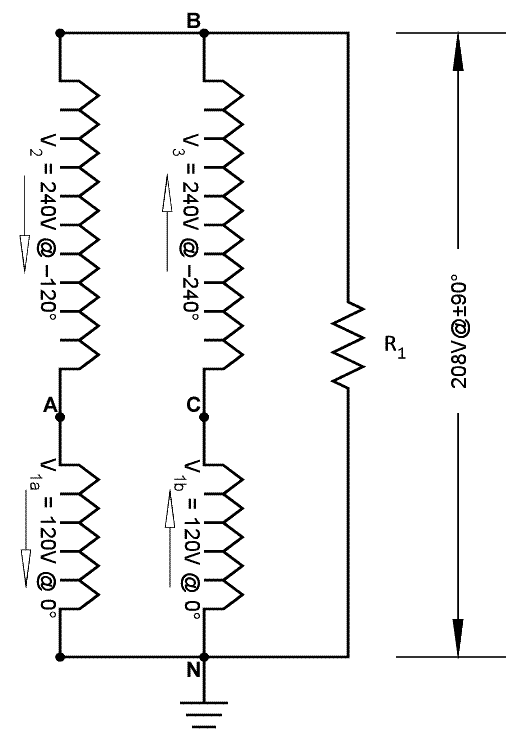
As for diagram, I wasn't sure whether you wanted one similar to your typed depiction or one aranged in delta configuration, so I made both... but in my opnion the enhanced "typed" one gives a false impression because the windings aren't oriented to their voltage phase angles.

hi-legcircuit2.gif


hi-legcircuit1.gif
 

mivey

Senior Member
In my opinion, this represents typical Delta operation as far as the polarities are shown. Ignore the phase angles.And this represents the currents caused by a highleg-to-neutral load, again as your polarities show and ignoring the phase angles.


What I'm saying is that both events are occurring simultaneously. The loop drawing shows typical Delta operation, and the neutral-referenced drawing shows the highleg-to-neutral load current. Comments?
They are the same circuit. It is just a change in where the meter leads are placed to measure the voltages.

Add: more after lunch. I'm late.
 

nakulak

Senior Member
ok,

given:

1) I acknowledge the fact that due to phase angle, and coil loading, use of the stinger isn't most efficient use of transformer
2) balancing the loads on the transformer using stinger loads isn't as efficient as using the 120/240
3) correct breakers are used (non slash)

If (4) an allowance is made for these facts when loading the transformer,

My question is:

is there any other compelling reasons you have not stated (or that I missed) to NOT use 208 loads on a high leg ?

(I'm looking for compelling technically correct, NEC, or faulty logic/catastrophic failure danger reasons, not "because that's the way I was taught" reasons )
 
Last edited:

Smart $

Esteemed Member
Location
Ohio
Now, both of these drawings (electrically the same) show standard Delta currents. Now flip the arrows on the B-C phase and the C-N half of C-A without changing your phase angle numbers. What happens?
One cannot simply flip the arrows and not flip the phase angle too. As mivey said, it is the same as flipping your meter leads. B-C would change to 60?, while C-N would be 180?. Doing so has no effect on current other than how it is measured.

hi-legcircuit3.gif
 

mivey

Senior Member
I don't believe it does (...but I could be wrong)

Wouldn't that mean for the one-half winding that the current opposes the voltage that the power factor would be less than zero (90?<θ<270?). I'm of the impression that is impossible... or if it is possible, it would impact the voltage through reverse induction (or induction cancellation).
The current has a phase angle of 90?. The 1/2 winding voltage C-N is at 0? (90? difference) and the full winding voltage B-C is at 120? (30? difference).

BTW, you need to swap the "A" and "C" in the second drawing to match the foward rotation of the first drawing.
Now let's say we additionally connect a 3? load. How do you envision the current through the split/center-tap winding???
By superposition, they would overlap and you would get the sum of the 1-ph & 3-ph currents in the 1/2 winding.
Overall, before we get to far, let me ask a question. Is there any reactive current involved in supplying this circuit or not? Please go into as much detail as you can.
There is a phase angle between the coil voltages and the current running through them. See response above.
As for diagram, I wasn't sure whether you wanted one similar to your typed depiction or one aranged in delta configuration, so I made both... but in my opnion the enhanced "typed" one gives a false impression because the windings aren't oriented to their voltage phase angles.
Thanks for the drawings. The second one has reverse rotation and the first one does not. See note above about swapping "A" and "C" in the second drawing.
 

mivey

Senior Member
One cannot simply flip the arrows and not flip the phase angle too. As mivey said, it is the same as flipping your meter leads. B-C would change to 60?, while C-N would be 180?. Doing so has no effect on current other than how it is measured.
Precisely.
 

mivey

Senior Member
Now, both of these drawings (electrically the same) show standard Delta currents. Now flip the arrows on the B-C phase and the C-N half of C-A without changing your phase angle numbers. What happens?
You would not have a closed delta system.
 

LarryFine

Master Electrician Electric Contractor Richmond VA
Location
Henrico County, VA
Occupation
Electrical Contractor
One cannot simply flip the arrows and not flip the phase angle too. As mivey said, it is the same as flipping your meter leads. B-C would change to 60?, while C-N would be 180?. Doing so has no effect on current other than how it is measured.
Okay, forget all that for now.

Look at the two arrows on the CT'ed C-A secondary:
I believe that, for highleg-to-neutral loads only, the current will be as the arrows show, but not with one at 180 degrees relative to the other; I think the currents will attempt to flow in phase, but in opposing directions.

You're showing voltage developement and normal current flows, as if reading voltage or normally-connected 1ph or 3ph loads. I think the 208v load current would cuase heating in the core and in the secondary windings.

Current is not supplosed to flow in what would basically be bucking in two windings sharing one core. I may be way off base here, but that's what my instincts tell me. Let me see if I can make an example:

What would happen if we took a typical 120/240v transformer secondary, with four leads, X-1, X-2, X-3, and X-4, and connected them in series for 120/240v as usual, except the reverse the leads from one winding?

In other words, instead of connecting X-2 and X-3 together, we connect X-2 and X-4 together, and attempt to use X-1 and X-3 as the 240v output, with X-2/X-4 as the neutral. To me, this is almost the same thing.
 

mivey

Senior Member
Look at the two arrows on the CT'ed C-A secondary:
I believe that, for highleg-to-neutral loads only, the current will be as the arrows show, but not with one at 180 degrees relative to the other; I think the currents will attempt to flow in phase, but in opposing directions.
Agreed
You're showing voltage developement and normal current flows, as if reading voltage or normally-connected 1ph or 3ph loads. I think the 208v load current would cuase heating in the core and in the secondary windings.
Maybe. I only had a series reactance but there might be something missing by leaving out the parallel reactance. It is usually left out for sizable loading as it has such a small contribution.
Current is not supplosed to flow in what would basically be bucking in two windings sharing one core. I may be way off base here, but that's what my instincts tell me. Let me see if I can make an example:

What would happen if we took a typical 120/240v transformer secondary, with four leads, X-1, X-2, X-3, and X-4, and connected them in series for 120/240v as usual, except the reverse the leads from one winding?

In other words, instead of connecting X-2 and X-3 together, we connect X-2 and X-4 together, and attempt to use X-1 and X-3 as the 240v output, with X-2/X-4 as the neutral. To me, this is almost the same thing.
You would just have 120 volts as the coils would be paralleled.

I'm going to have to chew on the opposing flux thing as I may not be thinking clearly.
 

mivey

Senior Member
ok,

given:

1) I acknowledge the fact that due to phase angle, and coil loading, use of the stinger isn't most efficient use of transformer
2) balancing the loads on the transformer using stinger loads isn't as efficient as using the 120/240
3) correct breakers are used (non slash)

If (4) an allowance is made for these facts when loading the transformer,

My question is:

is there any other compelling reasons you have not stated (or that I missed) to NOT use 208 loads on a high leg ?

(I'm looking for compelling technically correct, NEC, or faulty logic/catastrophic failure danger reasons, not "because that's the way I was taught" reasons )
With your givens, I can't see any reasons at thise point.

Larry is thinking of some kind of catastophic failure or heating danger. I have not been able to picture it.

The floor is open if you have some insights that may clear things up.
 

mivey

Senior Member
No, they'd be in series, but with one 120v winding reversed; i.e., swap X-3 and X-4 without swapping X1- and X-2.
Parallel.
Transformer windings:
..mmmmmmmm....mmmmmmmm
.|.........\/.........|
.|.-120+.../\..-120+..|
x4.......x2..x3......x1


X2-X3:
..mmmmmmmm....mmmmmmmm
.|.........\/.........|
.|.-120+.../\..-120+..|
x4.......x2__x3......x1
.|....................|

.|_______-240+________|


X2-X4:

..mmmmmmmm....mmmmmmmm
.|.........\/.........|
.|.-120+.../\..-120+..|
x4________x2.x3______x1
.|...........|........|
.|_-120+_____|........|
.|....................|
.|_____________-120+__|
 

mivey

Senior Member
I think I see what you mean. Instead of connecting the load between x4-x2 and x3-x1 you mean connect the load between x3 and x1. In that case you have zero volts:

X2-X4:
..mmmmmmmm....mmmmmmmm
.|.........\/.........|
.|.-120+.../\..-120+..|
x4________x2.x3.......x1
.............|........|
.............|........|
.............|__-0+___|
 
Status
Not open for further replies.
Top