3 phase Delta High Leg Single Phase Load

Status
Not open for further replies.

jim dungar

Moderator
Staff member
Location
Wisconsin
Occupation
PE (Retired) - Power Systems
Well i dont agree with load does not effect phase to voltage and transformation from a delta source to a wye...

It is too bad that you do not understand that the load connection does not affect the connection of the source.

I do not understand this portion of your statement
which is commonly not done ever in electrical .

In a delta system current does not circulate around the delta.

Wrong, current can and does circulate around in a closed delta.

By using the connection to the high leg your creating a unbalance which effects voltage current and its reactive to currents passing thur other phases .
Can you show me someplace where it has been said, transformer loading, both magnitude and balance,does nto affect the voltage?

Also if you hook up a wye winding motor to a delta source it will burn up motor and even heat up the transformer to damage the winding insulation by reactance and its a drop on winding voltage output.
This is absolutely wrong.

Ferroresonance is any entirely different topic than 'high-leg' transformer loading, please start a new thread.
 

ohmhead

Senior Member
Location
ORLANDO FLA
It is too bad that you do not understand that the load connection does not affect the connection of the source.SEE BELOW

I do not understand this portion of your statement


Wrong, current can and does circulate around in a closed delta. ITS IN THIS ARTICLE

Can you show me someplace where it has been said, transformer loading, both magnitude and balance,does nto affect the voltage? NEXT POST


This is absolutely wrong. ITS IN THIS ARTCLE

Ferroresonance is any entirely different topic than 'high-leg' transformer loading, please start a new thread.

Well read this article http://www.epuniversity.org/tech/w3.html


All you questions to my post are in this one article unless i have misread .

Heres one as example from the field we turn on new unloaded transformer say 2500 kva new first time we get 495 to 504 volts on secondary line to line but when loaded to say 45 % voltage goes to 480/475volts why ?
 
Last edited:

jim dungar

Moderator
Staff member
Location
Wisconsin
Occupation
PE (Retired) - Power Systems
There are an unbelievable number of errors in that article.

It reads like it was written for non-electrical people to get a very basic understanding of 3-phase concepts.

In a delta system, current does not circulate around the delta.

Current definitely can flow around a delta. But for very basic analysis, using many assumptions, it is easier to ignore this path.

This feature of return path of current through the phases in a delta system makes electrical distribution challenging: Phase to ground faults makes the load imbalanced because of the uneven distribution of phase currents in the system.
This is only true if there are at least two phase to ground connection, otherwise there is no complete current path. Depending on the location of these connections it is very probably that the system will not be significantly imbalanced.

As mentioned earlier, neutral carries the phasor (algebraic) sum of 3 phase current which is zero.
Wrong, it is a vectorial not an algebraic addition.

The electrical configuration of the source and the load should be same under any circumstances. That is, a Delta load should be connected to only a delta source and a Wye load should only be connected to a wye source.
Wrong again. Wye loads are regularly connected to delta distributions. The load configuration does not affect that of the source.

Wye system (Load) connected to Delta system (Source):
At the load end, the return current takes the neutral path. But the neutral of the wye load has no connection to the delta source. The neutral at the load is connected to the ground. Now the return path of current is through the ground wire at the load. It creates ground loops in the electrical system, and this causes the ground wire to carry current in the electrical system. This phenomenon breaks all laws of fundamental electricity. Ground is designed for safety and it should not carry any current.
This is so unbelivably wrong, I don't know where to start. The NEC does not allow the neutral of a load to be connected to ground. But, even if this connection existed, no current will flow on it as there is no completed path back to the delta source.

If this article is your primary reference source, it is not worth carrying on a discussion.
 

ohmhead

Senior Member
Location
ORLANDO FLA
There are an unbelievable number of errors in that article.

It reads like it was written for non-electrical people to get a very basic understanding of 3-phase concepts.

[/FONT]
Current definitely can flow around a delta. But for very basic analysis, using many assumptions, it is easier to ignore this path.

[/FONT]This is only true if there are at least two phase to ground connection, otherwise there is no complete current path. Depending on the location of these connections it is very probably that the system will not be significantly imbalanced.

[/FONT]Wrong, it is a vectorial not an algebraic addition.


[/FONT]Wrong again. Wye loads are regularly connected to delta distributions. The load configuration does not affect that of the source.

Wye system (Load) connected to Delta system (Source):
[/FONT]This is so unbelivably wrong, I don't know where to start. The NEC does not allow the neutral of a load to be connected to ground. But, even if this connection existed, no current will flow on it as there is no completed path back to the delta source.

If this article is your primary reference source, it is not worth carrying on a discussion.


Well Jim i did not write it so lets look at what i may not know as a person who has no degree in electrical i can only look at what is in front of me .

But the addition of sums ?

Im looking at the Standard Handbook for Electrical Enginners 11TH edition

MCgraw & Hill i know you have it page 2-7 states

Kirchhoffs Law = 1. Algebraic sum of the currents toward any junction
2. Algebraic sum of the voltage around any closed path in the network is zero .

Does that sound ok ?

Now this is a old book today it may be different where interested in knowing i will look into each and if i find that there incorrect i will write them and let them know what there doing wrong .
 

jim dungar

Moderator
Staff member
Location
Wisconsin
Occupation
PE (Retired) - Power Systems
Well Jim i did not write it so lets look at what i may not know as a person who has no degree in electrical i can only look at what is in front of me .
That article is wrong and should not be used in a technical discussion.

But the addition of sums ?

Im looking at the Standard Handbook for Electrical Enginners 11TH edition

MCgraw & Hill i know you have it page 2-7 states

Kirchhoffs Law = 1. Algebraic sum of the currents toward any junction
2. Algebraic sum of the voltage around any closed path in the network is zero .

Does that sound ok ?
Yes that sounds close. But the article you quoted says 'phasors (algebraic)". If they had said the 'algebraic sum of the phasors', while still not technically correct, it is closer..

How about Kirchoffs Law #1: The sum of currents entering a junction is equal to the sum of the currents leaving the junction. Or even, the (algebraic) sum of the absolute values of the phasors meeting at a junction is zero.

Now this is a old book today it may be different where interested in knowing i will look into each and if i find that there incorrect i will write them and let them know what there doing wrong .
The reference book I am using is more than 45 years old, so age has nothing to do with it.
 

ohmhead

Senior Member
Location
ORLANDO FLA
That article is wrong and should not be used in a technical discussion.


Yes that sounds close. But the article you quoted says 'phasors (algebraic)". If they had said the 'algebraic sum of the phasors', while still not technically correct, it is closer..

How about Kirchoffs Law #1: The sum of currents entering a junction is equal to the sum of the currents leaving the junction. Or even, the (algebraic) sum of the absolute values of the phasors meeting at a junction is zero.


The reference book I am using is more than 45 years old, so age has nothing to do with it.

Well Jim iam looking into this now i agree with your problem with current flow in a delta my books says delta current flow path a/b thur a winding but it also says and can also take the path thur winding b/c dividing up branching off two paths from a its a parrallel and series path of flow ? that is different the what the web page said so you are correct hes wrong .

I guess we have to look at what we read today now iam trying to learn more of the stuff i never had a chance to learn so i trust ones site to post good info if there going to explain it why dont they do it the right way :-?
 
Last edited:

ohmhead

Senior Member
Location
ORLANDO FLA
Well heres a question that has not been answered yet .

When we turn on a transformer brand new no load 2500 kva 480 3 ph wye secondary voltage is higher than nominal as in code ? like 490v to 504v but can be also different like the phases are not the same by 10 volts and this is tapped or measure at secondary on the lugs ?

My thoughts its the wiring or capacitance of attached feeders with no load on transformer but id like the real answer .
 

mivey

Senior Member
...In that case you have zero volts...
That is not to say in our case the voltages on the 1/2 windings "collapse" to zero. Even if the flux from the opposing secondary currents cancels out in the core going back to the primary, we still have the magnetizing flux from the primary. This "balanced" secondary flux just would not link to the primary.

We do not need secondary current to have secondary voltage. Consider the unloaded transformer where there is zero secondary current, but the magnetizing flux is still there to create the voltage. Any secondary current just produces some additional linkage flux and results in some primary current that is above and beyond the loss currents.

One more thought, even if no mutual flux is generated to go back to the primary, there would still be some leakage flux that would be different for each 1/2 of the winding. All of these pieces would settle out such that all power is accounted for, but I have not made those calcs to see what the values of the leakage flux might be.

I guess the biggest issues with using the high leg are:

1) You run the risk of damaging single phase equipment not designed for 208 volts (hacks anyway).
2) Finding the proper breaker.
3) Why use 208 when you have 240 available?
4) Ensuring adequate transformer size.
5) Voltage unbalance.

As I see it, none of these issues would necessarily mean you could not or should not ever use the high leg for single phase loads as they all have a way they can be addressed.
 
Last edited:

mivey

Senior Member
Well heres a question that has not been answered yet .

When we turn on a transformer brand new no load 2500 kva 480 3 ph wye secondary voltage is higher than nominal as in code ? like 490v to 504v but can be also different like the phases are not the same by 10 volts and this is tapped or measure at secondary on the lugs ?

My thoughts its the wiring or capacitance of attached feeders with no load on transformer but id like the real answer .
Voltage is high because of no load and/or high primary voltage.

Voltage unbalance is due to unbalanced primary voltage or unbalanced impedances
 

kbsparky

Senior Member
Location
Delmarva, USA
I've seen this done, in a restaurant. They bought some used single phase coolers which were rated 208 Volts only. Those coolers were originally installed in places where 208 Y 3 phase power was available.

This restaurant had delta-connected 3 phase power, so the only way to make the coolers work properly was to either connect to the high leg and neutral, or install some buck transformers.

They connected to the high leg, and this setup worked fine for years.

In a case like this, using one side of a 2-pole 240 Volt rated breaker was the most cost-effective option, as opposed to buying new coolers, or installing a transformer. :cool:
 

LarryFine

Master Electrician Electric Contractor Richmond VA
Location
Henrico County, VA
Occupation
Electrical Contractor
This "balanced" secondary flux just would not link to the primary.
If not, then how could each half of the secondary "add" it's 120v (at its vector angle which results in subtraction, of course) to its adjacent 240v secondary to create the 208v?

Here's my original question: with an open Delta, this would 'work' within the limits of the transformers' capacities and the CT's one's ability to handle the imbalance.

But, with a full Delta, don't we have two of these 1-1/2-secondary 208v supplies in parallel, but with the current directions opposite what they normally are in some way?

I can't help but wonder what effect the 208v-loads' currents would have on the transformers, unless the answer is just that they would consume their share of power.
 

mivey

Senior Member
If not, then how could each half of the secondary "add" it's 120v (at its vector angle which results in subtraction, of course) to its adjacent 240v secondary to create the 208v?
It is just a voltage in series so it will add. The flux back to the primary is canceled and causes no increase in primary current (excluding some loss current).
Here's my original question: with an open Delta, this would 'work' within the limits of the transformers' capacities and the CT's one's ability to handle the imbalance.

But, with a full Delta, don't we have two of these 1-1/2-secondary 208v supplies in parallel, but with the current directions opposite what they normally are in some way?

I can't help but wonder what effect the 208v-loads' currents would have on the transformers, unless the answer is just that they would consume their share of power.
The current flowing through the transformer will have some minor effect due to the internal impedance. Since the currents are in opposition, the flux is balanced out and the primary coil only sees the net flux which is the original magnetizing flux (plus some additional flux due to internal impedance.

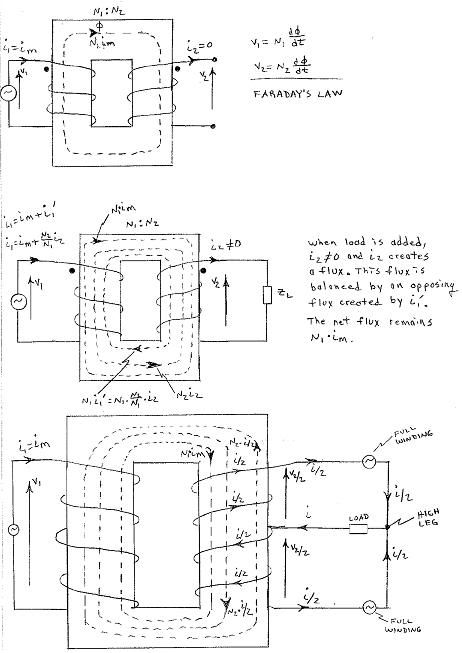
Consider the following three drawings. The first shows the magnetizing flux that creates the secondary voltage but no secondary current.

The second shows what normally happens when we add a load. The secondary current creates some additional flux which is linked to the primary. The primary current increases by i1' to create an opposing flux to balance out the added flux. The original magnetizing flux remains.

The third shows what happens with the high leg. Both sides of the winding create flux. This flux is balanced out and does not cause a current increase in the primary because the primary only sees the original magnetizing flux.

A more accurate model would have the internal impedances but I think you would agree that it is academic.


HighLegFlux.jpg
 

LarryFine

Master Electrician Electric Contractor Richmond VA
Location
Henrico County, VA
Occupation
Electrical Contractor
Your thord drawing triggers my question:

You show the currents shared by the high-leg load with the arrows pointing toward each other. What happens to those currents when they combine in the CT'ed secondary?
 

mivey

Senior Member
Your thord drawing triggers my question:

You show the currents shared by the high-leg load with the arrows pointing toward each other. What happens to those currents when they combine in the CT'ed secondary?
They both have the same phase angle and sum together to produce a resulting current with twice the magnitude of the individual currents.
 

rattus

Senior Member
Your third drawing triggers my question:

You show the currents shared by the high-leg load with the arrows pointing toward each other. What happens to those currents when they combine in the CT'ed secondary?

Larry, draw the currents (I/2) as two loops, one CW and the other CCW. They combine in the load to form the load current (I) and split again at the CT. If we assume that Vbn = 208V@90 with a resistive load, the phase angle of the load current will also be 90 degrees.

This means that (I) will be 90 degrees out of phase with Van and Vcn. (I) will be 30 degrees out of phase with Vba and Vbc. Good reasons not to use the high leg voltage.

Yep, I know this notation is confusing, but it is quite valid.
 

ohmhead

Senior Member
Location
ORLANDO FLA
Larry, draw the currents (I/2) as two loops, one CW and the other CCW. They combine in the load to form the load current (I) and split again at the CT. If we assume that Vbn = 208V@90 with a resistive load, the phase angle of the load current will also be 90 degrees.

This means that (I) will be 90 degrees out of phase with Van and Vcn. (I) will be 30 degrees out of phase with Vba and Vbc. Good reasons not to use the high leg voltage.

Yep, I know this notation is confusing, but it is quite valid.

Well actually rattus this makes it easyer for me to understand than all those formulas on other post and as iam trying to understand this more on how a delta really works .
 

ohmhead

Senior Member
Location
ORLANDO FLA
Well Mivey that makes it more clear i actually see it on paper which a electrician can follow :grin:

This was the best example of current flow thur hi L !
 
Last edited:
Status
Not open for further replies.
Top