RayS
Senior Member
- Location
- Cincinnati
well, I'd like to add a different view. I voted current thru 2 would be greater.
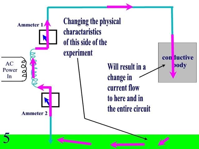
Since we are talking electrostatic only, you are basically just charging one or the other, and since the ground has a much higher capacity to store a charge, i think more current would flow there.
Imagine if the circuit was built using 2 different spheres, one much larger than the other. Assume no coupling between the spheres. You would have minute charging/discharging flows to each, but more toward the bigger one.
")