Capacitor Bank failure mode?

Status
Not open for further replies.

JWCELECTRIC

Senior Member
Location
Massachusetts
Bob,

Call the Techs @ Cuttler-Hammer and send them all the info you have about the bank along with the photos (very helpful), and see what they suggest as far as testing or replacement. They may even have it on record thru shop submittals on this project. If it is dated equipment and you don't know much about the history of situation, I would replace the unit only if it is needed based on PF history and if the store is being hit with penalties on low PF.
 
Quote:
Originally Posted by zog
Did you check the resistance of the internal discharge resistors?

No, I would not have thought to and would not know how.

LW: The little beige thingies on top of each capacitor connecting in a triangle. Each should have the same value of resistance.


Quote:
Originally Posted by zog
How about discharge time?

No, I would not have thought to and would not know how.

LW: Connect V-meter while power ON, disconnect and time voltage decay.


Quote:
Originally Posted by zog
Did you measure the capacitance of all terminal combonations?

No, I would not have thought to and would not know how.

LW: you would need a special instrument for that, ordinary meters do not have the capability.

Well that was easy


Quote:
Originally Posted by weressl
Did you have a bonding wire between the panel and the cap enclosure?

Yes, a 1/0 copper.

LW: That makes the fault even more mysterious as to why the grounding wire wasn't capable to carry the full fault. That is presuming that the burnt mark was not there BEFORE the ground wire was attached.


Quote:
Originally Posted by weressl
I think you want to megger at 1000V.

I have no doubt your right, I am a newbie with megameter, trying first to 'do no harm'.
LW: Be careful with the megger, it could charge up your capacitors and could give you the jolt of the lifetime.:D


Quote:
Originally Posted by weressl
Sounds like an arcing fault due to switching surge or harmonic ringing.

Is there a reasonably priced cure?

LW: the harmonic ringing is an unavoidable result of untuned capacitors applied to the whole system where the inductance varies. One cap per motor would be the way to go. It is more of a problem where there is very little inductance in the system and you are close to or even passed unity power factor.


Quote:
Originally Posted by weressl
What a heck does it supposed to accomplish in this service anyway?

This is a moderate sized super market in a chain of about 20, they have capacitors at many of their locations. They feel it is worth it.

Figure 15 to 25 compressors, all of them going on and off all the time but almost always some are running 24/7.

LW: Is their billing contains KVA charges or power factor penalty? If not, it is doing nothing for them.
 
Last edited:

steve66

Senior Member
Location
Illinois
Occupation
Engineer
A lot of multimeters have capacitance meters on them - even some of the really cheap ones. I'm not sure exactly how many "Farads" a 20 KVAR cap (or a 200 KVAR cap) should be, but it should be something that can be calculated, or maybe CH can tell you. The discharge resistors might throw off a cheap meter also, while a good meter will still read the capacitance, and show the parallel resistance as a "quality" factor.

If you are worried about tripping the main, you could always take the unit back to the shop. I don't see any reason why a 480V cap couldn't be connected to 208V.

And if you are concerned about an arc flash, you could connect power to the caps one at a time through a 40A or smaller breaker.
 

jim dungar

Moderator
Staff member
Location
Wisconsin
Occupation
PE (Retired) - Power Systems
You are correct but I can find no reason for those marks in the wireway at all, the conductors tested fine and look OK.

If it was easy I would not have had to ask. :smile:
Maybe the burn marks have nothing to do with the capacitor bank at all.
Current flowing on an improperly bonded wireway may have been trying to get to the capacitor's bonding conductor instead of from it.
 

iwire

Moderator
Staff member
Location
Massachusetts
The little beige thingies on top of each capacitor connecting in a triangle. Each should have the same value of resistance.

LOL, I know what a resister is. :D


Connect V-meter while power ON, disconnect and time voltage decay.

Well that I could figure out if I could power them up.

I assumed zog had a way in mind to do that without firing up questionable equipment.


you would need a special instrument for that, ordinary meters do not have the capability.

Makes sense


That makes the fault even more mysterious as to why the grounding wire wasn't capable to carry the full fault.

You bet, another reason why I was not about to just fire this thing back up.

That is presuming that the burnt mark was not there BEFORE the ground wire was attached.

Of course it is possible it was installed after but I think that is extremely doubtful.

However the lug terminating the EGC to the cap case is questionable, it looks like no paint was removed before it was installed. But there is no arc mark there and when I reading from the terminal to the case it shows very little resistance.

Be careful with the megger, it could charge up your capacitors and could give you the jolt of the lifetime.:D

I was very careful, I did not feel like getting belted, the resisters seemed to prevent the mega from charging the capacitors at all.


the harmonic ringing is an unavoidable result of untuned capacitors applied to the whole system where the inductance varies. One cap per motor would be the way to go. It is more of a problem where there is very little inductance in the system and you are close to or even passed unity power factor.

Understood.

There is no way they will do one cap per motor but we may be able to reduce the size of the single unit.


Is their billing contains KVA charges or power factor penalty?

Yes.

Electricity is a major portion of a supermarkets overhead and they try many ways to reduce costs.

In some stores they have an agreement with the power company to use the stores generators when the power company is having load problems. The power company can remotely start the generators and force an ATS transfer if they need to.
 

iwire

Moderator
Staff member
Location
Massachusetts
Maybe the burn marks have nothing to do with the capacitor bank at all.
Current flowing on an improperly bonded wireway may have been trying to get to the capacitor's bonding conductor instead of from it.

I considered that, but due to the layout it does not seem to be the case.

The EGC run with the feeder runs directly to the grounding bus in the switchgear, the conduit is firmly attached to that same switch gear.
 

zog

Senior Member
Location
Charlotte, NC
Wow, you guys were busy on this one last night, sorry doing yardwork all evening and crashed early but it seems LW took care of your questions.

At this point I would recommend you bring in a testing company, they test these all the time and will have all the right tools, and you can watch them and learn some stuff. This should be a quick job for them and cost you less than you think.

Check your PM box for some contacts.
 

jim dungar

Moderator
Staff member
Location
Wisconsin
Occupation
PE (Retired) - Power Systems
Your breaker is a current limiting 400A device, the fuses are 800A class T.

For faults less than 10kA the breaker will operate faster than the fuses. Past 10kA it is hard to tell.

You did not mention the settings for the service GFP, but assuming it is an ITI GF or a GE SS breaker set at 1200A 1s, it would trip before the breaker for faults between 1kA and 2.5kA.
 

mivey

Senior Member
A lot of multimeters have capacitance meters on them - even some of the really cheap ones. I'm not sure exactly how many "Farads" a 20 KVAR cap (or a 200 KVAR cap) should be, but it should be something that can be calculated, or maybe CH can tell you. The discharge resistors might throw off a cheap meter also, while a good meter will still read the capacitance, and show the parallel resistance as a "quality" factor.

If you are worried about tripping the main, you could always take the unit back to the shop. I don't see any reason why a 480V cap couldn't be connected to 208V.

And if you are concerned about an arc flash, you could connect power to the caps one at a time through a 40A or smaller breaker.
You could always verify the capacitor values using a lower voltage (fusing the input, of course). You would check one module at a time.

The calcs use the same formulas you would use for any set of capacitors. These are not some mysterious black-box capacitors secreted from behind the iron curtain :D
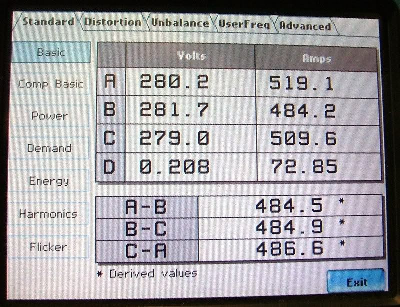
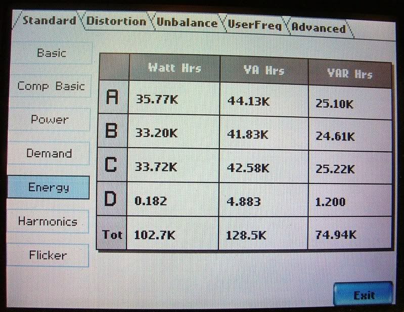
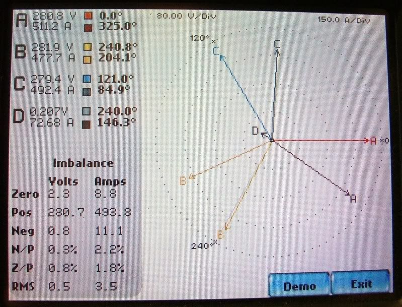
,so no need to call CH unless you want the exact value (the bank rating is most likely a rounded number). The currents will tell you if the capacitors are balanced.

You can have capacitors connected delta or wye. You can always find and equivalent wye or delta circuit. The formulas are (I have used some odd notation in the hopes it will clarify):

Capacitor Values & Rating (f is frequency):
Xc = 1 / (2 * Pi * f * C)
Xc_Wye = 3 * Xc_Delta
Xc_Delta = Xc_Wye / 3

Delta Connected:
kvar_total = 3 * V_line-line * Ic_delta / 1000
Ic_delta = I_line / sqrt(3) = VLL / Xc_delta
kvar_total = 3 * VLL^2 / (1000 * Xc_delta) = 3 * VLL^2 * 2 * Pi * f * C_delta / 1000
kvar_delta_leg = VLL^2 / (1000 * Xc_delta) = VLL^2 * 2 * Pi * f * C_delta / 1000

Wye Connected:
kvar_total = sqrt(3) * VLL * Ic_wye / 1000
Ic_wye = I_line = VLL / (sqrt(3) * Xc_wye)
kvar_total = VLL^2 / (1000 * Xc_wye) = VLL^2 * 2 * Pi * f * C_wye / 1000
kvar_wye-leg = VLL^2 / (3 * 1000 * Xc_wye) = VLL^2 * 2 * Pi * f * C_wye / (3 * 1000)

Example using Iwire's bank:
Looking at the pictures, you have 10 paralleled modules. The total is 200 kvar so that gives you 20 kvar per module, so:
20 = 3 * 480^2 * 2 * pi * 60 * C_delta / 1000 giving a value of 76.75uF per capacitor in each leg of each module.

Xc_delta = 1 / (377 * 76.75E-6) = 34.56

I_line = sqrt(3) * Ic_delta = 1.732 * 480 / 34.56 = 24.06 amps (241 amps for the complete bank).

So what if we hook one module up to a 120/208 3 phase source for a test?
I_line = sqrt(3) * Ic_delta = 1.732 * 208 / 34.56 = 10.42 amps. We would want protection for about 150% of this value (15.6 amps) so use a 20 amp fuse or breaker.
 

iwire

Moderator
Staff member
Location
Massachusetts
OK I have leaned some more, I ended up talking with the guy who installed this capacitor and was there when the fault happened. The reason I could not find a problem is that the bad capacitor bank has already been removed and the one I was looking at has never been energized.

So really I could just fire it up but all you engineer types have got me a bit concerned it is oversize and will do more harm then good. It happens I have access to a nice PQ recording meter and installed it on site today.

Here are some snapshots of PQ when I got it hooked up. I was hoping someone could decipher what all this info means. :smile:

RBPQ1.jpg


RBPQ2.jpg


RBPQ3.jpg


RBPQ4.jpg


RBPQ5.jpg
 

iwire

Moderator
Staff member
Location
Massachusetts
Oh I guess I should provide a legend. :smile:

Channel A = Volts & Amps Phase A

Channel B = Volts & Amps Phase B

Channel C = Volts & Amps Phase C

Channel D = Volts from Neutral to Ground

Channel D = Amps on Neutral
 

electricalperson

Senior Member
Location
massachusetts
the current harmonics look pretty crazy. im not much of a help at all but i was just wondering, is the PQA hooked up in the main panel? what type of loads does this place have?
 

iwire

Moderator
Staff member
Location
Massachusetts
It is a medium sized supermarket, a lot of 3 phase compressors.

The meter is connected on the load side of the service disconnecting means, all power runs through it.


The capacitor bank is off line.
 
Status
Not open for further replies.
Top