Parallel conductors

Status
Not open for further replies.

GoldDigger

Moderator
Staff member
Location
Placerville, CA, USA
Occupation
Retired PV System Designer
A current source is perfectly happy if the voltage is the same. It would work just fine with superconductors with no voltage drop whatsoever.
Perfectly true, but very hard to get your mind around for most people.
There will be a voltage drop in the conductor between the GTI and the grid connection, but it does not play any role in setting the output current.
 

jaggedben

Senior Member
Location
Northern California
Occupation
Solar and Energy Storage Installer
...

A real utility network is very complicated, because all the other neighboring services affect the voltage at your service point. They have a standard to supply power within a given percentage tolerance above and below nominal at your service point, and the utility-owned transformers are tuned to get as close as possible to nominal for each customer. It is a moving target to maintain this.
...

Although it is perfectly valid to start with the current values, you will at the end have to modify those current values to satisfy the constraint equation that the voltage drops on all of the parallel segments (end-to-end) are equal. (That is what ggunn left out of his analysis.)
You cannot just end up with two or three different voltages on parallel components. :)

Practically speaking, I think we can represent the utility at the service point as an idea voltage source and the inverter as current source that can inject exactly its max output. (The inverter really does behave this way.) Actually I don't believe you even need to consider the nominal utility voltage. That's what I ended up doing with the example; the givens are just 200A from the PV, 500A load, and the resistances. When I saw what kind of numbers were necessary to make the voltage drop roughly equal, I realized that a more sophisticated calculation wasn't really required.
 

Smart $

Esteemed Member
Location
Ohio
This is a "lumped system", where the resistances represent a round-trip feeder resistance. A proper setup would have a lot of duplicate resistors, to represent the return path and all the phases.
You don't need all phases... 1? is sufficient.

The ground point in a PSPICE model is more analogous to neutral, the way we use it. It is a point at which we define voltage to equal zero, and all connections to it to be electrically continuous with it. Unlike ground for us, which shouldn't carry current under ordinary circumstances, current can flow to and from a ground point in a spice model.

If you only define one ground point in the PSpice model, there will be no current in the connection to it.
I don't need a lesson in how the ground point(s) work in SPICE.
 

Smart $

Esteemed Member
Location
Ohio
Practically speaking, I think we can represent the utility at the service point as an idea voltage source and the inverter as current source that can inject exactly its max output. (The inverter really does behave this way.) Actually I don't believe you even need to consider the nominal utility voltage. That's what I ended up doing with the example; the givens are just 200A from the PV, 500A load, and the resistances. When I saw what kind of numbers were necessary to make the voltage drop roughly equal, I realized that a more sophisticated calculation wasn't really required.
I'm not going to say that both service conductors will balance at 250A at the load end, but to get true-to-life values, the conductor resistance would have to be dynamic. In everyone's calculations or simulations it is static.

For example, you said the tap to load will be 350A while the other service conductor will be 150A. I'm willing to bet the true-to-life values are closer to the average.... but I'm not going to say drastically closer. The tap to load section will have a higher resistance due to handling more current... and the untapped conductor will have less resistance because current is lower. This will affect the VD (or ID) calc's...

Discussing it further is really pointless from my perspective. Such an installation is non-compliant no matter what the current levels are.
 

GoldDigger

Moderator
Staff member
Location
Placerville, CA, USA
Occupation
Retired PV System Designer
The effect in terms of excess current in the tap to load section of the tapped conductor will vary considerably with the location of the tap.
A tap close to the service will have the least effect on the current in the tap-to-load section of the conductor while a tap close to the load will have the largest effect, but on a smaller length of conductor.
As Smart$ stated, non-compliant regardless.
 

Carultch

Senior Member
Location
Massachusetts
The effect in terms of excess current in the tap to load section of the tapped conductor will vary considerably with the location of the tap.
A tap close to the service will have the least effect on the current in the tap-to-load section of the conductor while a tap close to the load will have the largest effect, but on a smaller length of conductor.
As Smart$ stated, non-compliant regardless.

In the scenario of exporting power, the effect is reversed.

During export of power, backfeeding the service transformer:
Closest to the load = least imbalance, spread out over a long length
Closest to the utility source = most imbalance, but over a local length only

During on-site consumption of PV power + utility power (as discussed):
Closest to the utility source = least imbalance, spread out over a long length
Closest to the load = most imbalance, but over a local length only
 

ggunn

PE (Electrical), NABCEP certified
Location
Austin, TX, USA
Occupation
Consulting Electrical Engineer - Photovoltaic Systems
The effect in terms of excess current in the tap to load section of the tapped conductor will vary considerably with the location of the tap.
A tap close to the service will have the least effect on the current in the tap-to-load section of the conductor while a tap close to the load will have the largest effect, but on a smaller length of conductor.
As Smart$ stated, non-compliant regardless.

Non-compliant with what section of code, specifically?

You guys get it that I am playing devil's advocate here, right? I have always tapped all the conductors in a set.
 

GoldDigger

Moderator
Staff member
Location
Placerville, CA, USA
Occupation
Retired PV System Designer
Non-compliant with what section of code, specifically?

You guys get it that I am playing devil's advocate here, right? I have always tapped all the conductors in a set.
We go back to the "identical termination" rule, I think. There is no clear and direct wording regarding taps.
 

Smart $

Esteemed Member
Location
Ohio
Non-compliant with what section of code, specifically?

You guys get it that I am playing devil's advocate here, right? I have always tapped all the conductors in a set.
310.10(H)

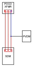
Refer to diagram...

unequal%20parallel.gif


The blue conductor above and the red conductor below the tap point are parallel conductors with respect to the PVDM to transformer (or vice versa) circuit. Blue goes direct to POCO trannie, red gets there in a round-about way (which way the current goes is irrelevant). Compare to requirements of 310.10(H)(2).
 

jaggedben

Senior Member
Location
Northern California
Occupation
Solar and Energy Storage Installer
I agree with Smart$. The inverter output circuit is paralleled in a non-compliant manner.

Also, at the risk of re-opening another can of worms, I consider the tap a new set of service entrance conductors. Would anyone allow a new set of service conductors to be installed this way if it weren't for a PV sytem? I don't think so.
 

ggunn

PE (Electrical), NABCEP certified
Location
Austin, TX, USA
Occupation
Consulting Electrical Engineer - Photovoltaic Systems
I agree with Smart$. The inverter output circuit is paralleled in a non-compliant manner.

Also, at the risk of re-opening another can of worms, I consider the tap a new set of service entrance conductors. Would anyone allow a new set of service conductors to be installed this way if it weren't for a PV sytem? I don't think so.
Here as in many other places you have to sort of stand on your head to interpret the code for PV. If the connection were to be taking power from the service, there would be no question that they would be service entrance conductors. FWIW, 690.13(C) says, "Each PV system disconnecting means shall not be required to be suitable as service equipment."
 

jaggedben

Senior Member
Location
Northern California
Occupation
Solar and Energy Storage Installer
Here as in many other places you have to sort of stand on your head to interpret the code for PV. If the connection were to be taking power from the service, there would be no question that they would be service entrance conductors. FWIW, 690.13(C) says, "Each PV system disconnecting means shall not be required to be suitable as service equipment."

Well, I don't want to debate that again, since we pretty much exhausted it last time. (And it really doesn't come down to that section, IMO, which applies to DC conductors.)

However, look at the definition of an inverter output circuit, repeated redundantly in 690, 694, and 705, all with the same bad grammar which clouds the meaning. It applies to conductors between the inverter and the utility, and so regardless of how the conductors are classified with respect to being service conductors, what you have here is an inverter output circuit that is paralleled without meeting 310.10(H).

The code needs a lot of changes, IMO. Of that I'm sure.
 
Status
Not open for further replies.
Top