brother said:
I suppose an amprobe wouldnt get it either if neutral was balanced.
Take the following EXTREME scenerio in COMMECIAL buildings. You have a 3 hot 1 common neutral circuit, Black, red, blue (full boat). Your working on the 'blue' circuit' . You shut it off/lock out tag out, the 'blue circuit'.
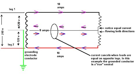
You test the circuit and it is off and also put an amprobe on the neutral and you have a 'true' neutral' no amps cause the black and red circuit is perfectly balanced.
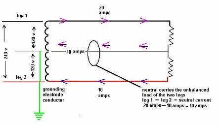
On two legs of a "full boat", the neutral will not have zero amps, but will have exactly the same current as the missing third leg had when it was on and the three legs balanced.
Of course the black and red circuit do NOT pass through the same j box nor are in the same conduit leaving the panel so there is NO hint of that neutral being shared.
If the black and red legs are not in this box, then neither would there be their shared neutral. The hots and neutrals of any circuit must always be grouped. In other words, any place the neutral is accessible and carrying more than one circuit's load, the corresponding hots will be in the same box.
There is no excuse for not being aware that you are looking at a shared neutral. I've never opened a neutral junction that I didn't know was carrying current. A quick look inside the panel will tell you if the neutral is shared, and by which other circuits.
I always place shared-neutral-circuit breakers side-by-side, even if it requires re-labeling the panel, mainly because it minimizes the possibility of same-phasing ond overloading a neutral. I hate seeing three hots from a full-boat conduit land on breakers spread out in a panel.
Your argument is more towards the use of handle ties for shared-neutral circuits than it is against shared neutrals. The bottom line is that you should always be aware when you're looking at a neutral that supplies, or possibly supplies, more than one circuit.
Also that black and red circuit is on and carrying a LOAD (someone in another part of the commercial office is using their computer and copier).
Again, you should anticipate this, identify the other circuits, and lock-out and de-energize them, routinely.
You still treat the wires as being HOT even the neutral . . .
Yes, always.
Tell me what could have been done to AVOID frying that computer, you searched for the shared neutral, looked for and tested for, used an amprobe and u still had no hint of the neutral being shared. What else could you have done short of turning OFF the whole PANEL
")
??
I believe I have.
Im still learning so let me know.
That's the best thing you wrote. Keep up the great attitude!
infinity said:
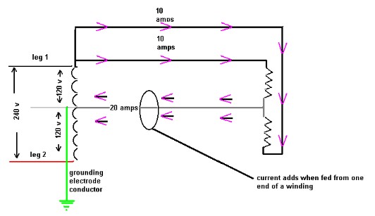
If the loads on the black and red circuit were perfectly balanced an open neutral would not cause the voltage at each computer to be 208 volts. They would effectively be in series and would divide the 208 volts between them.
For example if you had a 100 watt lamp on the black phase and a 100 watt lamp on the red phase, the loss of the common neutral would put the two loads in series with a voltage drop at each lamp of 104 volts. The lamps would not "fry" but would become noticeably dimmer.
True. But now, try the same experiment, but with one 100-watt load and one 1000-watt load.