More experiments on current flowing in earth

Status
Not open for further replies.

crossman gary

Senior Member
Note 1: I placed this thread in the NEC forum because the original "Grounding Electrode Conductor Question arose here. Moderators, if it needs to be moved, have at it!

Note 2: This is a follow-up to the thread: http://forums.mikeholt.com/showthread.php?t=115917

Did more experiments today. It rained hard on Saturday night, so there is water in the ditches and the soil is pretty wet... wetter than it was on Saturday morning when I did the original experiment. My thoughts were that this would make the earth conduct even better. I was right as will be shown.

I drove 3 more pipes into the ground at various places. These are 5 foot long 1/2" rigid pipes. I drove them in about 4 feet, leaving 1 foot sticking up.

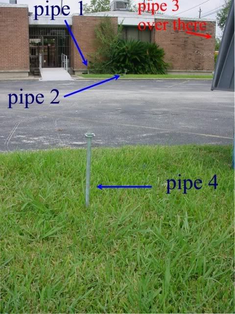
Here are photos of the locations.

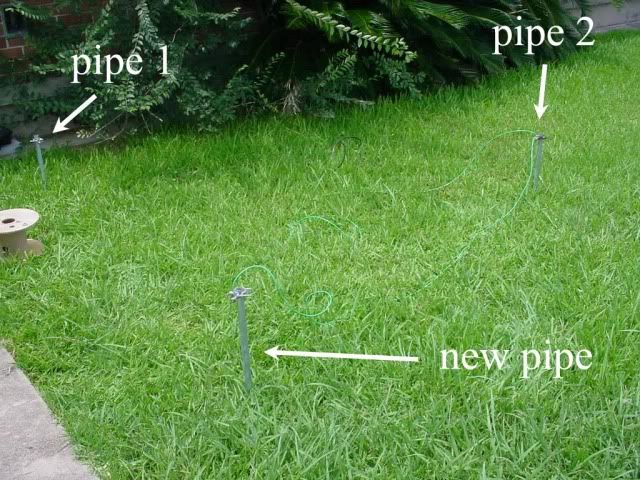
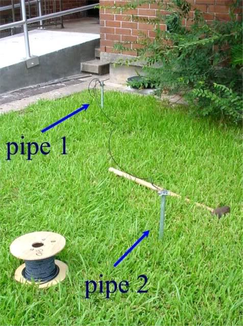
Pipe 1 is the pipe that I used on Saturday. It was driven in 3 feet, I went ahead and drove it down one more foot. As I mentioned, each pipe is 5 feet of 1/2" rigid, driven 4 feet into the ground. Pipe 2 is driven in the grassy area, about 6 feet from pipe 1. The photo was taken after I did pipe 1 and pipe 2 in parallel, hence the wire between them.

amh1and2.jpg


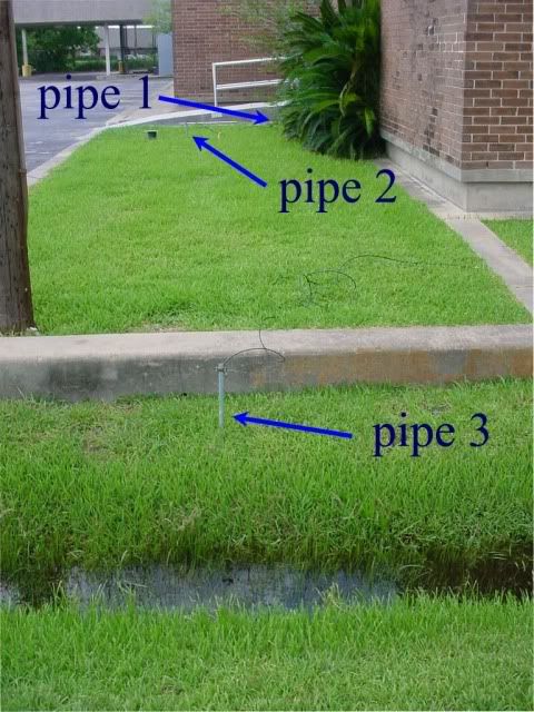
Pipe 3 was driven right next to the ditch. You can see there is water there. Plus, the city water main runs under there somewhere, I am guessing it is around an 8" steel pipe. I figured that this pipe should be pretty conductive at that location. BTW... the power pole right there... it has a bare ground wire coming down to about 2 feet above the soil, and it is cut off there. Nothing going in the soil.

amh3.jpg


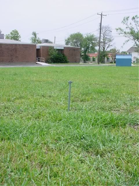
Pipe 4 was driven across the parking lot, about 60 feet from pipes 1 and 2. I figured this one wouldn't be too good. It is in a 1 acre vacant lot. There is a dumpster sitting to the right, you can see the lid in the photo.

amh4.jpg


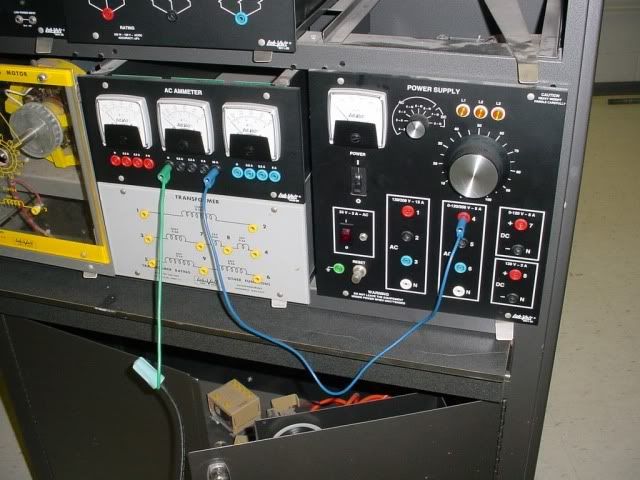
Here are photos of the lab equipment:

AMHsupply.jpg


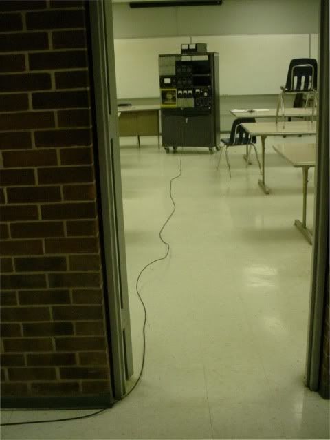
And the #8 wire going outside to the pipes.

amhwire.jpg


The power supply has a varible voltage 0 to 120v supply. In the previous experiment, I thought that the OCPD was 15 amps. As someone mentioned, I believe it was Hurk27, that the 15 amps was for the non-variable supply. he was right. The 0 to 120 volt unit says 0-120v 5 amps. So we will take that to mean the OCPD for that portion is 5 amps.

I tested each pipe seperately by connecting the #8 to the pipe, then slowly turning up the voltage and recording the current measurements. Now, the meters are fairly small analog type, so the numbers I give you are only accurate to about 1/2 an amp. That isn't a concern, as the overall trend is what is important.

After I did each pipe seperately, I connected pipe 1 and 2 in parallel and tested them together.

Here is a table showing my results:

Volts....Pipe 1...Pipe2...Pipe 3...Pipe 4...Pipe 1 and 2 in parallel

20........3..........2.........4..........2................5

40........7..........5.........8..........5................11

60........10........7.........11.........8...............trip

80.......trip........9........trip........10

100..................trip..................trip

Pretty significant current! The 5 amp OCPD was tripping at around 11 amps.

Again, the recent rain probably had a marked effect on these results. If we have another 2 week drought, I feel the currents would be much lower.

Another thing I am wondering about is if it matters that the pipes were freshly driven or if they have been in the ground for months. I wonder if that could affect the contact between the earth and the pipe. Does the "grip" and "pressure" of the earth to the pipe diminish over time as the compressed soil spreads?

Any comments?
 

Buck Parrish

Senior Member
Location
NC & IN
Nice pics , thanks.
It would be neccessary to use 5/8 eight ft. long grd. rods, plates or approoved method. Otherwise 4 ft. deep would not be prudent.
 

don_resqcapt19

Moderator
Staff member
Location
Illinois
Occupation
retired electrician
You have earth that is a lot more conductive than what is in many parts of the country.

I have done experiments like that for a few of the grounding classes that I have taught. I used 8' x 5/8" ground rods with about 6" of rod exposed. The most current I have had flow was a bit over 5 amps using a 120 volt source, and that was after 3 or 4 rainy days. The current on the others, under drier, conditions, was less than 3 amps.

I would expect that the contact between the pipe and the earth gets better over time, but not sure.
 

crossman gary

Senior Member
I found the following from Mike Holt on the net:

http://www.mikeholt.com/technical.p...esistance - It's Not What You Think (12-30-99)

Here are some snippets from the above:

Mike Holt?s Experiments

I tested the ground resistance of a single 5/8th ground rod installed vertically 8 feet in the earth at my workshop. The soil was very moist due to many days of rain...

One final thing, I was curious to see if I attached an energized (120 volt) wire directly from a 1-pole 15-ampere breaker to one of the parallel ground rods (the ground rods were isolated from the electrical system) if my circuit breaker would trip? The results:
One ampere of fault current flowed from the 120 volt source through the grounding electrode at my workshop, through the earth to the power supply (utility transformer).


I accept the above. The soil and/or POCO/shop electrodes had high resistance.

I accept Don's results which are close to Mike holt's results.

However, these results cannot be used to make a blanket statement about soil resistivity, nor can they be used as the basis for a belief system about current flow between electrodes. It completely depends on the local conditions.

I am certain that Mike Holt (nor Don) did not imply or intend that his results would apply anywhere else in the world. But some folks seem to have applied this result to all electrodes/soil conditions everywhere.

My results were completely different than Mike Holt's. My soil conditions are apparently completely different.

Do not make a mistake and assume I am championing using dirt as a fault path. No way. The proper grounding of equipment as detailed in the NEC is no doubt the proper way to do things.
 

bob

Senior Member
Location
Alabama
Gary
You might try to compare a delta vs straight line installation. You see the delta configuration specified on many large jobs.
 

quogueelectric

Senior Member
Location
new york
I found the following from Mike Holt on the net:

http://www.mikeholt.com/technical.p...esistance - It's Not What You Think (12-30-99)

Here are some snippets from the above:

Mike Holt’s Experiments

I tested the ground resistance of a single 5/8th ground rod installed vertically 8 feet in the earth at my workshop. The soil was very moist due to many days of rain...

One final thing, I was curious to see if I attached an energized (120 volt) wire directly from a 1-pole 15-ampere breaker to one of the parallel ground rods (the ground rods were isolated from the electrical system) if my circuit breaker would trip? The results:
One ampere of fault current flowed from the 120 volt source through the grounding electrode at my workshop, through the earth to the power supply (utility transformer).


I accept the above. The soil and/or POCO/shop electrodes had high resistance.

I accept Don's results which are close to Mike holt's results.

However, these results cannot be used to make a blanket statement about soil resistivity, nor can they be used as the basis for a belief system about current flow between electrodes. It completely depends on the local conditions.

I am certain that Mike Holt (nor Don) did not imply or intend that his results would apply anywhere else in the world. But some folks seem to have applied this result to all electrodes/soil conditions everywhere.

My results were completely different than Mike Holt's. My soil conditions are apparently completely different.

Do not make a mistake and assume I am championing using dirt as a fault path. No way. The proper grounding of equipment as detailed in the NEC is no doubt the proper way to do things.
Nice job always back up theory with facts like this. It separates the book worms from the explorers. Most electricians would be looking for a 5/8 - 8' rod because that is the standard minimum in many poco requirements. That is why others are asking for this.
 
Last edited:

SEO

Senior Member
Location
Michigan
Gary very informitive project. The conductivity of the soil in your test must be off the map. We have areas that are all sand and driving a ground rod is like placebo to the grounding system.
 

crossman gary

Senior Member
Nice job always back up theory with facts like this. It separates the book worms from the explorers. Most electricians would be looking for a 5/8 - 8' rod because that is the standard minimum in many poco requirements. That is why others are asking for this.

Thanks quog, for the support.:smile:

On the ground rod issue - I wasn't intending this to be a test of ground rods. I was really testing the conductivity of the soil in my area when subjected to fault current. Therefore I purposely used the 1/2" rigid four feet in the ground as an "even worse than an 8 foot rod" scenario.

The building already has a complete electrode system and the source xfmr is tied to that.

I proposed an example in the other thread on this subject:

Hypothetical: An unskilled electrician is installing a receptacle out in a field, 50 feet from the building. He digs a trench, drops in some 1/2 pvc, turns it up with a 90, and puts a metal bell box on that. To support the bell box, he drives a 5 foot piece of unistrut into the soil, leaving one foot sticking up as a support for the box. He pulls a hot and a neutral, but no EGC. If the hot got smashed under the cover, how much current would flow through the earth back to the building electrode.

That is what I intended to accomplish with the experiment.

I am certain that in most areas of the country, the current flow would be pretty small. In my area this morning, it would have been a significant current....

Now... was it enough to trip a 15 amp breaker? Probably not. But it was alot more than most people would believe.

If I had actually used 8 foot deep ground rods, and paralleled them or used three in a delta config, heck, it might have been enough to trip a 20 amp breaker.
 

crossman gary

Senior Member
Gary very informitive project. The conductivity of the soil in your test must be off the map. We have areas that are all sand and driving a ground rod is like placebo to the grounding system.

Thanks Steve.

I would think that dry sand or gravel would be the worst case. I agree that the ground rod would be about pointless. Well.... actually TWO ground rods by code!:roll:

More about this black clay soil: When we have been under a long period with no rain in the summer, the clay will bake into a hardened mass like concrete. It is almost impossible to dig in with a shovel. Seriously hard.

As the moisture level increases after a rain, it turns into this "perfect consistency for digging" where the shovel goes in, and you pull back a bit, and a nice neat chunk comes out, then you turn the shovel over and the chunk falls right out. Hand-digging a ditch in these conditions is a complete breeze.

But with more rain and moisture, it soon turns into this devilish frustrating goo that sticks to absolutely everything, I mean this stuff is like contact cement. You can beat your shovel on a concrete curb or whatever, the goo just won't come off. Horrible. About the only way to manage this condition is to dip the shovel in a bucket of water between shovel-fulls.

I have never tested the clay when it was dry and hardened. I purposely chose a time after we had a good rain to do the test. It did not dissappoint me.;)
 

dbuckley

Senior Member
In the world of HVDC, in many older systems the entire monopole return current or the balance of a bipole current imbalance traves by means of ground electrodes. We're talking currents of thousands of amps here travelling distances of hundreds of miles via that soily thing under our feet. It is possible to build ground electrodes that have quite low impedences, but it isn't just a rod or two stuck eight feet in :)
 

don_resqcapt19

Moderator
Staff member
Location
Illinois
Occupation
retired electrician
...
I am certain that Mike Holt (nor Don) did not imply or intend that his results would apply anywhere else in the world. But some folks seem to have applied this result to all electrodes/soil conditions everywhere.

My results were completely different than Mike Holt's. My soil conditions are apparently completely different.

Do not make a mistake and assume I am championing using dirt as a fault path. No way. The proper grounding of equipment as detailed in the NEC is no doubt the proper way to do things.
Gary,
Nice work with this testing.

Actually the idea for me to do this came from Mike...I was at a class at LU 134's training center and he did it. Then I used it a few times for my class, but you are correct. These tests are very site specific and only apply for that exact location.

There are systems that do use the earth as a circuit conductor. Single Wire Earth Return (SWER) are used for power distribution in some areas of the world. Just one high voltage conductor is run and the transformer is connected to this conductor and to the earth at the remote location.

There are also some studies that say that the utilities under size their primary neutrals and about 1/3 of the primary neutral current returns to the source via the earth...one source of "stray voltage".
 

mivey

Senior Member
Gary,

I read both of your dirty threads and found them to be interesting, especially the reactions. It is another study in listening to what someone is saying vs what you think they are saying.

I think there was some surprise that you were able to make such a great connection as we usually have to put forth more effort to reach mother earth. It certainly stirred the pot. :grin:

If you feel froggy one day, how about repeating your experiment and making a soil resistivity measurement at the same time?

I would be interested to see how much the resistivity and the connection changes from your wet to dry conditions. I'm wondering if you go from great to good or great to poor, etc. As for the connection, I seem to recall that some of the Ufer experiments were in a sandy/desert area and the better connection had to do with the concrete holding moisture?

If the resistivity stays about the same, but the connectivity drops then the wet dirt helps the connection. I wonder if it matters if the rod is driven on a dry day vs a wet day makes any difference (should we water our ground rods?)

One more interesting bit of info might be a core sample. The USDA offered this as a free service when we were investigating a ground water issue at our home. The tool was just a manually operated pipe/corer on a long rod (similar to a water cut-off tool), but the best part was having the soil expert there to identify the soil types and characteristics as the samples went deeper.

We have sandy loam here and some yellowish clay and our connections are so-so, I would guess. My mother's home is further north and has dark red clay and I would think make a much better connection, but I have never thought about it too much before.
 

crossman gary

Senior Member
Hi Mivey,

Thanks for the response.

As for taking an earth resistance measurement, I don't necessarily have the "approved" equipemnt to do that. I did go outside today and do some more testing.

I drove another pipe next to Pipe 1 and Pipe 2, making a delta arrrangement. I then measured the resistance from pipe to pipe, and it was about 25 ohms between each. In other words, the reading between any two pipes was 25 ohms. These are driven in 4 feet, and each pipe is about 6 feet apart.

Photo:

aamhd.jpg


I then did the voltage test to pipe 1 by itself just to see if the conditions were similar to Monday. It hasn't rained any since Saturday, and the water is not standing in the ditch anymore, but the ground still feels saturated with moisture. This clay soil really doesn't drain well. When it is soaked with water, it takes a long time to dry out.

20 volts = 3 amps
40 volts = 7 amps
60 volts = 10 amps
80 volts = trip

This isn't too far off from the original tests, so moisture conditions are similar.

Then I connected the 3 pipes together in the delta config and applied the voltage:

20 volts = 7
40 volts = trip

Extrapolating to 120 volts, that would be 42 amps if the relationship holds. Remember, this is three 5 foot long, 1/2 rigid pipes driven into the soil a depth of 4 feet each.

Then I drove another pipe out in the middle of the lot next door.

aamhlot.jpg


I ran a #8 wire all the way to it, then did the test.

20 volts = 1 amp
40 volts = 4 amps
60 volts = 7 amps
80 volts = 9 amps
100 volts = 11 amps
100+ volts = tripped

The soil is still very conductive even three days after the rain.

Mivey, you bring up good questions. I would also like to do this test after a long drought, just to see what changes. I am leary of leaving the pipes in the ground due to the tripping hazard. Maybe I will pound them down flush, and then I can dig around them to connect to them later.

I mentioned earlier about the "glueiness" of this clay when saturated. It sticks like crazy, and I think this really helps to lower the resistance of the soil/pipe interface.
 

crossman gary

Senior Member
Hey Gene!

Good to have you here. Go ahead and register and you can actually participate in these discussions too instead of just reading. I'm sure the members would love to have you.

Thanks!
 

steve66

Senior Member
Location
Illinois
Occupation
Engineer
Uhhhh.....I'm not sure if your power supply is grounded, & I'm not sure what you are using for a return, but isn't that like really, really, really dangerous to anyone who walks by??
 

mivey

Senior Member
Uhhhh.....I'm not sure if your power supply is grounded, & I'm not sure what you are using for a return, but isn't that like really, really, really dangerous to anyone who walks by??
That's what they tried to tell Tesla.
 

crossman gary

Senior Member
Well, yes, now that you mention it....

Although... considering the conductivity of the soil here, the actual voltage from the pipe to the earth in the vicinity of the pipe may not be all that much (regardless of other's statements about the "touch potential")

That is a darned interesting question and I suppose I am going to have to figure out a safe way to measure the voltage from the pipe to the dirt.

Experiment time!!!

Back to your question of safety.... This building is vacant during the day, only me and 2 others. Nobody was walking around near the pipes.
 

crossman gary

Senior Member
Okay.... how about if I drive another pipe about 2 feet from one of the existing pipes, and then attach a voltmeter between the pipes. Then I will energize one of the pipes and see what voltage exists to the other pipe.

Very very interesting question, and it applies directly to the question of connecting equipment to earth to prevent electrical shock.... connecting the equipment to earth puts the earth and the equipment at the same potential(?) Some have said that it doesn't help at all. I am figuring it depends on the local conditions. If the soil/pipe resistance is very low, then the potential difference between the two should be low.
 

crossman gary

Senior Member
Uhhhh.....I'm not sure if your power supply is grounded, & I'm not sure what you are using for a return

Power supply is grounded.... 208Y/120 with neutral. The return is through the dirt, back to the electrode system and any other conducting object in the vicinity which is grounded and connected back to the utility ground.

Tons of paths everywhere and who knows where current was traveling...

Heck, it could have been traveling to the service of the house across the street, up their electrode, up to the POCO ground, across the street overhead, and into my building via the service entrance neutral.

DISCLAIMER: Kids, don't try this at home. Experiements like this should be left to the professionals who have the knowledge and daring to safely conduct them.
 
Status
Not open for further replies.
Top