You are using an out of date browser. It may not display this or other websites correctly.
You should upgrade or use an alternative browser.
You should upgrade or use an alternative browser.
California Three-ways
- Thread starter chris1971
- Start date

- Status
- Not open for further replies.
ultramegabob
Senior Member
- Location
- Indiana
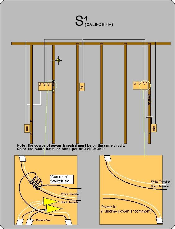
you run power and neutral to the traveler screws on each three way switch, and then a single wire from each common on each three way to the light, depending on what position the switches on in, you will wind up with one of these combinations at the light..... PN on, PP off, NP on, NN off. this set up is usually only found in Knob and Tube wiring.
Edit- it is important for both switches to be on the same circuit, or at least the same phase, or you will wind up with 240v at the light...
Edit- it is important for both switches to be on the same circuit, or at least the same phase, or you will wind up with 240v at the light...
Last edited:
- Location
- Illinois
- Occupation
- retired electrician
I found that out after we had replaced a 30 amp, 120 volt service with 100 amp, 120/240 volt service. The lights were very bright....for about a second....
Edit- it is important for both switches to be on the same circuit, or at least the same phase, or you will wind up with 240v at the light...
Howard Burger
Senior Member
- Location
- N of Anchrage, AK
Use the search option of this forum for more information. It was discussed several times in the past, with diagrams.
kbsparky
Senior Member
- Location
- Delmarva, USA
So now the underlying question here is: Could such a setup be legal powering a fixture that utilizes a GU24 CFL bulb, where there is no exposed "screw shell" ?

So now the underlying question here is: Could such a setup be legal powering a fixture that utilizes a GU24 CFL bulb, where there is no exposed "screw shell" ?
Nope.
404.2(B).
- Location
- Windsor, CO NEC: 2023
- Occupation
- Hospital Master Electrician
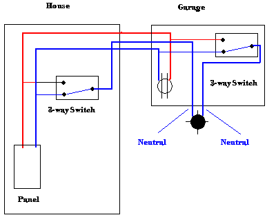
Anyone familiar with California three-way switching? If so, does anyone have a wiring diagram that shows how they are wired?
This is what I call a California threeway.
I can see where if you had never seen this before you might be scratching your head for awhile.
.......once you pick yourself off the ground from getting zapped.
ultramegabob
Senior Member
- Location
- Indiana
Why not just do it right? :roll:
I doubt anyone on here is intending on installing a new three-way with this method, it sure helps to understand how it works when you run across them.
Here in Ohio we call them Michigan 3-ways. One thing about them,once you figure it you never forget it!
I've heard many monikers for them. Farmer, Handyman, Michigan, Illinois, California, Power-Beyond..... I'm sure I could remember more, but it's too early in the morning yet.
RICK NAPIER
Senior Member
- Location
- New Jersey
I found these mostly on old BX cables. My father gave me the problem when I was in 8th grade telling me to draw a layout for 3-ways that had only a 3 wire between switches but a hot and neutral wire at each location. I forget how long it took me to figure it out but it was a long time. A side note the old mercury switches would blow up when put on these circuits since the travellers would tempoarily make contact when the tube splashed.
al hildenbrand
Senior Member
- Location
- Minnesota
- Occupation
- Electrical Contractor, Electrical Consultant, Electrical Engineer
So, Chris, given the responses, was this what you were looking for?Anyone familiar with California three-way switching? If so, does anyone have a wiring diagram that shows how they are wired?
Reason I ask is that the basic method shown, in the responses to your question, I've always known as a Carter.
There is a "travelling bus" arrangement that requires a minimum of four wires that I was taught (as an apprentice) was called a California 3 way.

peter d
Senior Member
- Location
- New England
Here in Ohio we call them Michigan 3-ways. One thing about them,once you figure it you never forget it!
That's not surprising. There is no love lost between Michigan and Ohio.
")
LarryFine
Master Electrician Electric Contractor Richmond VA
- Location
- Henrico County, VA
- Occupation
- Electrical Contractor
You can do that with only two conductors between the switches when there are a hot and neutral in each box.My father gave me the problem when I was in 8th grade telling me to draw a layout for 3-ways that had only a 3 wire between switches but a hot and neutral wire at each location.
Feed one switch with the hot, use the two conductors as travelers, and pick up the neutral in the other box.
- Status
- Not open for further replies.