Calculation of neutral current

Status
Not open for further replies.

rattus

Senior Member
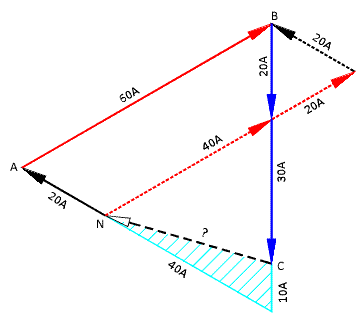
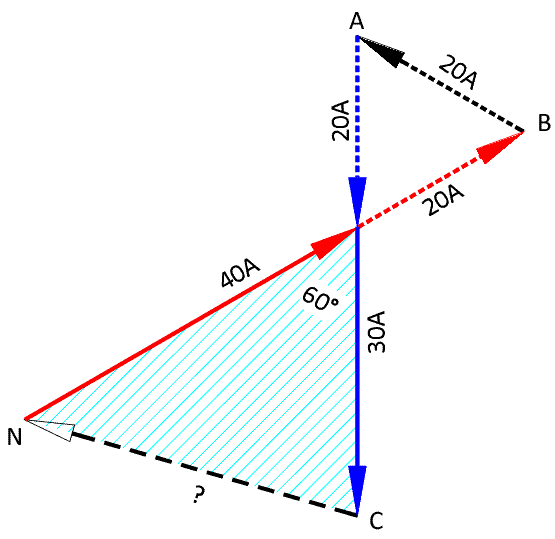
This question was on the PE exam. The neutral current is the sum of all the currents on each leg (phase), so therefore it would be Ia<-45 + Ib<-30 +Ic<-45. You must use the phase angle with positive and neg., with cos and sine. The reason is because some phases are lagging, and some are leading. This is why your P.F. for each phase is different.

With that said, if the loads were balanced, the sum of Ia<-45 + Ib<-30 +Ic<45 would equal zero, but as you already know the neutral carries the unbalanced current when the load is unbalanced.

Sorry, this was something they drilled into us on the PE exam, and there were 5 questions on this alone. Thank God that horrible test is over....selling circus peanuts, here we come! LOL :D

Lady, you must reference the phase angles to the phase voltages. For example, the angles 0, 120, and 240 yield the following equations.

Ia<-45 + Ib<90 + Ic<285 = In
 

jghrist

Senior Member
With that said, if the loads were balanced, the sum of Ia<-45 + Ib<-30 +Ic<45 would equal zero, but as you already know the neutral carries the unbalanced current when the load is unbalanced.
As rattus said, the current angles you give are in relation to each phase voltage angle. You have to add the voltage angle to get the absolute current angle before adding the currents.

If you mean by "if the loads were balanced" that " if the magnitude of each phase were equal", then the sum of the currents would not equal zero with different power factors.
 

Smart $

Esteemed Member
Location
Ohio
...one could draw the phasors such that two sides of the triangle intersect[/COLOR...


Yes it can. It also proves crossman's premise on subtracting the smallest from all three and working with the balance of the other two with only the law of cosines and no "grind"...

Nformula2.gif
 

rattus

Senior Member
Yes it can. It also proves crossman's premise on subtracting the smallest from all three and working with the balance of the other two with only the law of cosines and no "grind"...

Nformula2.gif

Smart, the attached diagram is what I had in mind. The point is that the order in which you draw the phasors may change the diagram, but not the result.
 

Lady Engineer

Senior Member
Location
New Jersey
Lady, you must reference the phase angles to the phase voltages. For example, the angles 0, 120, and 240 yield the following equations.

Ia<-45 + Ib<90 + Ic<285 = In

Geez...ok guys, I held up the liquor store. They are correct, you do that to add the angles, I forgot that part.

jghrist, you might have read too much into it, that's why I said use sine and cosine with the phase angle. If you add it vectorly, all three phases should equal zero, if it's balanced. Of course adding the magnitude will not equal zero, then using 0, -120, 120 would not be a factor.

Current and Voltage are not lines, they are vectors....
 
Last edited:

david luchini

Moderator
Staff member
Location
Connecticut
Occupation
Engineer
For example, the angles 0, 120, and 240 yield the following equations.

Ia<-45 + Ib<90 + Ic<285 = In

Check my math, but this would yield (from the OP):

50<-45 + 40<90 + 40<285 = 56.97

From post #2:

Welcome to the forum :)

58.86A


Why the discrepancy? I came up with 58.86A for the solution also by using the angles Van= <0, Vbn= <-120, and Vcn= <120 so that the equation is:

50<-45 + 40<-150 + 40<165 = In = 58.86A.

It occurred to me that in the OP that if you assign A=red, B=yellow, C=blue you would get a different result than A=red, B=blue, C=yellow (In=58.86, In=56.97 respectively.)

Am I figuring this correctly?
 

Lady Engineer

Senior Member
Location
New Jersey
From post #2:


Why the discrepancy? I came up with 58.86A for the solution also by using the angles Van= <0, Vbn= <-120, and Vcn= <120 so that the equation is:

50<-45 + 40<-150 + 40<165 = In = 58.86A.

It occurred to me that in the OP that if you assign A=red, B=yellow, C=blue you would get a different result than A=red, B=blue, C=yellow (In=58.86, In=56.97 respectively.)

Am I figuring this correctly?

I think it still works, but for what you used is for a wye configuration, not delta. Unless he used delta...not sure, I have to check the original post.

Again, what I was trying to explain to Rattus is my main issue is to add the angles in vector form but he's right we must use the 0, -120, 120, but it wasn't quite understood.
 

david luchini

Moderator
Staff member
Location
Connecticut
Occupation
Engineer
I think it still works, but for what you used is for a wye configuration, not delta. Unless he used delta...not sure, I have to check the original post.

Again, what I was trying to explain to Rattus is my main issue is to add the angles in vector form but he's right we must use the 0, -120, 120, but it wasn't quite understood.

We both used an equation for the Wye configuration Ia+Ib+Ic=In. That is what the OP stated, three currents from line to neutral.

And we both used the angles of 0, -120, 120, but the solution is different. I think even though the result is different, either answer would be correct.
 

jghrist

Senior Member
jghrist, you might have read too much into it, that's why I said use sine and cosine with the phase angle. If you add it vectorly, all three phases should equal zero, if it's balanced. Of course adding the magnitude will not equal zero, then using 0, -120, 120 would not be a factor.
I wasn't implying that you meant to add the magnitudes. I thought that you might mean that if the phase magnitudes were all equal, then the vectors would add to zero. This is not true if the angles are not 120? apart. For instance, if all current magnitudes in the OP were 40, then:

40<-45 + 40<90 + 40<285 = 47.09<-34.87? <> 0
 

rattus

Senior Member
Check my math, but this would yield (from the OP):

50<-45 + 40<90 + 40<285 = 56.97

From post #2:


Why the discrepancy? I came up with 58.86A for the solution also by using the angles Van= <0, Vbn= <-120, and Vcn= <120 so that the equation is:

50<-45 + 40<-150 + 40<165 = In = 58.86A.

It occurred to me that in the OP that if you assign A=red, B=yellow, C=blue you would get a different result than A=red, B=blue, C=yellow (In=58.86, In=56.97 respectively.)

Am I figuring this correctly?

I get the same results. At this moment though, I can't explain it.
 

rattus

Senior Member
Learned something today!

Learned something today!

David, it appears that swapping loads between two phases produces different neutral currents. This is contrary to my intuition (which is often wrong). Now, if we plot out the current waves we might see that the different phase separations affect the way in which the currents cancel. I do believe the math is right in either case. It is so to speak a matter of phase sequence.

If all PFs are equal, we would not see this discrepancy.

Now, who will say they knew that all along?
 

Smart $

Esteemed Member
Location
Ohio
Smart, the attached diagram is what I had in mind. The point is that the order in which you draw the phasors may change the diagram, but not the result.
...and I did not challenge that. I merely added to it, as more-succinctly demonstrated in this revamping of the image...

Nformula3.gif
 

Lady Engineer

Senior Member
Location
New Jersey
I wasn't implying that you meant to add the magnitudes. I thought that you might mean that if the phase magnitudes were all equal, then the vectors would add to zero. This is not true if the angles are not 120? apart. For instance, if all current magnitudes in the OP were 40, then:

40<-45 + 40<90 + 40<285 = 47.09<-34.87? <> 0

Again, that's not what I said, either. What I said was you must use the phasor angle (implimenting sine and cosine)with the magnitude of the current, in my orginal post, and adding those values together, provided they are balanced, should equal zero.

That's why I said...they are vectors, that that's why you must use the phasor or angle with the magnitude to determine the neutral current.
 
Last edited:

LMAO

Senior Member
Location
Texas
Hi,

If you have a balanced 3 phase, wye, 4 wire and you have 10A rms 3rd harmonic in each phase, would these harmonics flow through neutral? And why?

thanks
 
Status
Not open for further replies.
Top