Art. 300.3

Status
Not open for further replies.

Dennis Alwon

Moderator
Staff member
Location
Chapel Hill, NC
Occupation
Retired Electrical Contractor
This is a wo part question--I thought I understood article 300.3 but I am having a bit of an issue with it. Here is the first paragraph

(B) Conductors of the Same Circuit. All conductors of the same circuit and, where used, the grounded conductor and all equipment grounding conductors and bonding conductors shall be contained within the same raceway, auxiliary gutter, cable tray, cablebus assembly, trench, cable, or
cord, unless otherwise permitted in accordance with 300.3(B)(1) through (B)(4).

Now does this mean if a grounded conductor is used in the circuit then it must be run with the circuit conductors? What I am getting at here is why are we allowed to run a switch loop down from a light with the feed in the ceiling-- thinking pipe here for the time being. It would appear by doing this electromagnetic field's are created except that the metal conduit would contain it but it still seems to violate 300.3(B). Input please

I know I never looked at it that way before but I have a job that has a issue with electromagnetic field's in a residence because the switch leg was run from a 4 way switch instead of fed at one end and switch legged out the other. This job is nm cable and I get high readings at the 4 way but not at the 3 ways.

Situation is 3 way feed- 4way in the middle other 3 way dead end-- switch leg in the 4 way. I realize the electromagnetic field is created because the neutral is run apart from the switch loop but why is it only showing at the 4 way?
 

suemarkp

Senior Member
Location
Kent, WA
Occupation
Retired Engineer
Yes it does. A switch loop doesn't require a grounded conductor and doesn't make EMF because you have current "coming" in one conductor and "going" in the other. They go opposite directions and cancel out. If you had a single conductor going to the switch, and a separate single conductor leaving the switch and those conductors were not run together in the same raceway or cable, then you'd get EMF and inductive heating.

In a 3-way, you still have currents that cancel -- either there is a "return" switched hot going the opposite direction, or you have a neutral in the cable which provides the canceling current going the other direction.
 

Smart $

Esteemed Member
Location
Ohio
Mark pretty much covered the issue, but I have to ask how you get a switch leg only in the middle of a 3-4-3...???
 

Dennis Alwon

Moderator
Staff member
Location
Chapel Hill, NC
Occupation
Retired Electrical Contractor
I don't understand how the hot wire and switch leg cancel as there is power going there and the neutral is in another cable away from it. There is in fact electromagnetic field's created by this install.

If I connect it the standard way the issue will not be there.

Smart --- If the first 3 way has the feed and a 3 wire cable over to the 4 way then the neutral is carried over in the 3 wire cable with the travelers. The far 3 way is dead end so now we have 2 - 3 wire cables at the 4 way and the switch leg to the light. The neutral from the first 3 way connects to the light neutral via the switch leg. The hot wire of the switch leg connects to the 3 wire going to the dead end and is the point wire. The other 2 are the travelers and get connected to the 4 way just as the pair from the other 3 way got connect to the 4 way.
 

Smart $

Esteemed Member
Location
Ohio
...
Smart --- If the first 3 way has the feed and a 3 wire cable over to the 4 way then the neutral is carried over in the 3 wire cable with the travelers. The far 3 way is dead end so now we have 2 - 3 wire cables at the 4 way and the switch leg to the light. The neutral from the first 3 way connects to the light neutral via the switch leg. The hot wire of the switch leg connects to the 3 wire going to the dead end and is the point wire. The other 2 are the travelers and get connected to the 4 way just as the pair from the other 3 way got connect to the 4 way.
Okay, the switch leg doesn't originate in the middle... it originates at the dead end 3-way and comes back to the middle.
 

Smart $

Esteemed Member
Location
Ohio
I don't understand how the hot wire and switch leg cancel as there is power going there and the neutral is in another cable away from it. There is in fact electromagnetic field's created by this install.

If I connect it the standard way the issue will not be there.

...
Don't know where your EMF is coming from.

Draw the circuit out and use arrows to indicate current flow as if a DC circuit. It will be accurate for every other half cycle and backwards for the other half. When you have opposing current arrows, the EMF of each conductor will cancel.
 

Dennis Alwon

Moderator
Staff member
Location
Chapel Hill, NC
Occupation
Retired Electrical Contractor
Okay, the switch leg doesn't originate in the middle... it originates at the dead end 3-way and comes back to the middle.


The switch leg comes down into the 4 way box and splices over to one 3 way while the neutral comes into that same box and travels to the other 3 way. Both traveling on the respective 3 wire cables
 

Smart $

Esteemed Member
Location
Ohio
The switch leg comes down into the 4 way box and splices over to one 3 way while the neutral comes into that same box and travels to the other 3 way. Both traveling on the respective 3 wire cables
I understand how it is wired. See my most recent post before this one.
 

Dennis Alwon

Moderator
Staff member
Location
Chapel Hill, NC
Occupation
Retired Electrical Contractor
I realize the electromagnetic field's between the conductors cancel but wouldn't there be a field between those wires and the remote neutral? The area in between should have electromagnetic field. It does....
 

Dennis Alwon

Moderator
Staff member
Location
Chapel Hill, NC
Occupation
Retired Electrical Contractor
What about the first part. Seems like the wording needs adjusting as it seems to not allow a switch loop-- I see no reason that it cannot be done but the wording could be taken literally
 

Smart $

Esteemed Member
Location
Ohio
I realize the electromagnetic field's between the conductors cancel but wouldn't there be a field between those wires and the remote neutral? The area in between should have electromagnetic field. It does....
The neutral is always with a conductor on the other side of the load: hot in supply; travelers from fed 3-way to 4-way; switch leg from 4-way to light outlet. The travelers to the dead end 3-way are with the switch leg. You always have a conductor with opposing current flow in proximity to the other.
 

Dennis Alwon

Moderator
Staff member
Location
Chapel Hill, NC
Occupation
Retired Electrical Contractor
The neutral is always with a conductor on the other side of the load: hot in supply; travelers from fed 3-way to 4-way; switch leg from 4-way to light outlet. The travelers to the dead end 3-way are with the switch leg. You always have a conductor with opposing current flow in proximity to the other.


This is what I thought but I cannot explain why we are getting the reading and we get it about 6 inches from the 4 way and no where else. I am perplexed but I know it will be gone when we do a permanent rewire and move the switch leg to the dead end 3 way. If you look at the articles about better living and emfs they even go so far as to say keep the neutrals and hots the same length in the panel. Nutty I know..... But they show the 3 ways to be wired as we normally do it and only that way-- feed one end and switch leg from the other.

BTW this is not a house I did- I got called in because the ec wired things where the neutral had multiple paths and it created magnetic fields in a few areas of the house. I fixed those and did not have the materials to permanently take care of the other problem.
 

Smart $

Esteemed Member
Location
Ohio
This is what I thought but I cannot explain why we are getting the reading and we get it about 6 inches from the 4 way and no where else. ...
Possibly because the current through the switch is in front and the switch leg and neutral are spliced and pushed into the back of the box. That little bit of not-in-near proximity is all it takes.
 

jxofaltrds

Inspector Mike®
Location
Mike P. Columbus Ohio
Occupation
ESI, PI, RBO
What about the first part. Seems like the wording needs adjusting as it seems to not allow a switch loop-- I see no reason that it cannot be done but the wording could be taken literally

It gets better. LOL

404.2 Switch Connections.
(C) Switches Controlling Lighting Loads. Where switches
control lighting loads supplied by a grounded general purpose
branch circuit, the grounded circuit conductor for the controlled
lighting circuit shall be provided at the switch location.
 

jxofaltrds

Inspector Mike®
Location
Mike P. Columbus Ohio
Occupation
ESI, PI, RBO
Situation is 3 way feed- 4way in the middle other 3 way dead end-- switch leg in the 4 way. I realize the electromagnetic field is created because the neutral is run apart from the switch loop but why is it only showing at the 4 way?

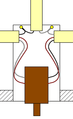
Dennis I had to read this many times before I saw the switch leg is in the 'middle'.

I only did this once because another electrician and I were trying to find different combinations that would work.

It makes sense but I do not have the engineering background to 'esplain' it!
 

Dennis Alwon

Moderator
Staff member
Location
Chapel Hill, NC
Occupation
Retired Electrical Contractor
Possibly because the current through the switch is in front and the switch leg and neutral are spliced and pushed into the back of the box. That little bit of not-in-near proximity is all it takes.


I don't think so or that would be the case everywhere as the neutrals are pushed back. You do get a reading at every switch with any significant load but if you move 1" from it it drops to zero. I believe she had someone come with sophisticated equipment and had a reading at 12"-- our meters did not pick it up that far away.
 

Smart $

Esteemed Member
Location
Ohio
I don't think so or that would be the case everywhere as the neutrals are pushed back. ...
But you don't have the neutral pushed back with another circuit conductor everywhere...

(pardon the crude drawing :blink:)

4-way.gif
 
Last edited:

jxofaltrds

Inspector Mike®
Location
Mike P. Columbus Ohio
Occupation
ESI, PI, RBO
I don't think so or that would be the case everywhere as the neutrals are pushed back. You do get a reading at every switch with any significant load but if you move 1" from it it drops to zero. I believe she had someone come with sophisticated equipment and had a reading at 12"-- our meters did not pick it up that far away.

What are the readings? 0.5mg? 140mg?

You can see where my hand is in relationship to the equipment. I forget what it was 2' away.

emf.jpg

But you don't have the neutral pushed back with another circuit conductor everywhere...

(pardon the crude drawing :blink:)

4-way.gif

I wish my good drawings came close to that.
 

Dennis Alwon

Moderator
Staff member
Location
Chapel Hill, NC
Occupation
Retired Electrical Contractor
But you don't have the neutral pushed back with another circuit conductor everywhere...

(pardon the crude drawing :blink:)


It does not look like that...:D They are folded on top of each other but sure at some point they are a bit apart. I am surprised that would give off that much electromagnetic field's outside the box. Certainly inside the box there would be a reading as there are in almost all of them. Maybe that's doing it--- I will certainly find out here in the next week or so.
 

Dennis Alwon

Moderator
Staff member
Location
Chapel Hill, NC
Occupation
Retired Electrical Contractor
What are the readings? 0.5mg? 140mg?

You can see where my hand is in relationship to the equipment. I forget what it was 2' away.


It is an interesting story but I believe the readings are about 12 mg. Fairly high by the standards-- some say over 2 mg is no good but if you use the meter next to a dimmer it will read 80 mg but pull away .5 in and it is zero. What I find interesting is that the home owner is bothered by this so much yet the stereo in her room when it is not turn on just plugged in gives off 70 mg next to the unit yet a switch in the wall giving off 12 mg bothers her. Heck the plug in carbon detector was emitting 56mg. Anyway she wants it fixed- well fix it.
 
Status
Not open for further replies.
Top