Transformer Calculations

Status
Not open for further replies.

faraday2000

Member
Location
fl
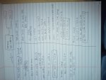
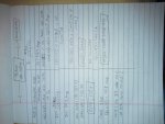
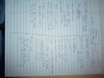
Hi I am a little confuse on how to use to NEC rules for transformer calculations..
Could anyone help me in checking if my calculations are right on the examples below


Transf Calc With 2 PNL.jpg Transf Calc With 1 PNL.jpg Transf Calc Without Sec OCPD.jpg
 

Attachments

  • Transf Calc With 2 PNL.jpg
    Transf Calc With 2 PNL.jpg
    134.3 KB · Views: 0
  • Transf Calc With 1 PNL.jpg
    Transf Calc With 1 PNL.jpg
    135.5 KB · Views: 0
  • Transf Calc With 2 PNL.jpg
    Transf Calc With 2 PNL.jpg
    134.4 KB · Views: 0

petersonra

Senior Member
Location
Northern illinois
Occupation
engineer
I am not real good at looking thru calcs like this and I did not check your math or your references but I don't see anything grossly wrong.

I would point out there is no requirement to accommodate the maximum load the transformer might be able to produce. Only that you protect the transformer and its associated primary and secondary wiring.

If the transformer secondary can put out 300A, you could put a 100A OCPD there and be code legal, as far as the transformer itself goes.
 
Last edited:

iceworm

Curmudgeon still using printed IEEE Color Books
Location
North of the 65 parallel
Occupation
EE (Field - as little design as possible)
Hi I am a little confuse on how to use to NEC rules for transformer calculations. ...

You don't look confused to me. The requirements for transformer (450), panel (408), and conductors (240) are treated separately. And you picked up on 240.21.C, no round up. Looks good.

One code isue: The primary conductors for the first two examples need to be protected by the primary OCP. Choosing a 225A CB requires conductor ampacity above 200A (follows from 240.4, 240.4.B) - in this case 4/0.

One design issue: Unless the transformer is a strange animal with a high inrush (TENV comes to mind), a 125% primary CB will work fine. This allows the primary conductors to be much smaller. As you noted is your third example, a 125A CB and #2 conductors will work fine.

ice
 

augie47

Moderator
Staff member
Location
Tennessee
Occupation
State Electrical Inspector (Retired)
Few problems, I believe.
As pointed out already, 225 is a standard size breaker. In your 1st example your primary conductor would need to be a 4/0 IF you use the 225 amp breaker.
Also, on your 1st example, if you are going to use a 300 amp OCP on your secondary, 240.21(C) prohibits the "next size up" rule, so your conductor(s) would have to have a rating of at least 300 amps.

On your 2nd example, I am of the opinion that you can not use a #2, with a 115 amp rating, on your 125 amp breaker. Although the Code allows the "next size up" the conductor must be sized for the load and there is nothing to prevent the lad reaching 125 amps.
 
Last edited:

iceworm

Curmudgeon still using printed IEEE Color Books
Location
North of the 65 parallel
Occupation
EE (Field - as little design as possible)
... On your 2nd example, I am of the opinion that you can not use a #2, with a 115 amp rating, on your 125 amp breaker. Although the Code allows the "next size up" the conductor must be sized for the load and there is nothing to prevent the load reaching 125 amps.

augie -
You lost me - I need a few clues.
First: Is this regulatory based or personal design philosophy?

Second: Are you saying that it is okay to use a #2 for the third example of feeding a load, but can not use a #2 if the xfm is feeding a panel?

My personal understanding of physics says one prevents overload through design. Generally, I am not a fan of designing to NEC minimums. However in this case (small, non-strange, transformers) 125% primary CB (round up) and conductors meeting 240.4 and 240.4.B work fine. This is true for panelboard or single load.

What am I missing?

ice
 

augie47

Moderator
Staff member
Location
Tennessee
Occupation
State Electrical Inspector (Retired)
ice:
That was the "in my opinion" :D
I think it's a fine line. IF you have a calculated load then I see no problem using 240.4(B).
In his case we have the transformer with unknown load. The 125% rule is for the protection of the transformer. In this situation with an "unknown" load there is nothing to keep the #2 from being loaded beyond it's ampacity.
 

iceworm

Curmudgeon still using printed IEEE Color Books
Location
North of the 65 parallel
Occupation
EE (Field - as little design as possible)
ice:
That was the "in my opinion" :D
I think it's a fine line. IF you have a calculated load then I see no problem using 240.4(B).
In his case we have the transformer with unknown load. The 125% rule is for the protection of the transformer. In this situation with an "unknown" load there is nothing to keep the #2 from being loaded beyond it's ampacity.

augie -
I'm okay with "in my opinion"

just teasing a bit - no intent to be mean.

I would file this one under the worm design guides of:
1. One starts at the load end and does the design moving back toward the source. By the time one gets to the xfm, all design calcs look like this.

2. If one is planning to overload the transformer (operate past 100%FLA) then, as you say, it is a good idea to upsize the conductors. I'd recommend also upsizing the OCP - and likely the room ventilation as well.

Now, what about my second question? If that is an "imo" also, that's okay as well.

ice
 

augie47

Moderator
Staff member
Location
Tennessee
Occupation
State Electrical Inspector (Retired)
I am 100% in agreement with worms design guide, and in that light I would have no problem with a #2c protected at 125 amps.
I looked a couple of times and I only see one instance where he was using a #2...I'll go back again with better glasses.
 
Status
Not open for further replies.
Top