common practice or code?

Status
Not open for further replies.

cainisunabel

Member
Location
Houston, TX
My employer asked me about dividers being used when a 120v switch is in a box with a 277v switch. He said the journeyman running the job told him dividers weren't required at these locations because of the insulation rating of the wire, which tells me the journeyman in question was using 303.3(C)(1) as his reference. My employer and supervisor both insist they have always used dividers in such situations but neither one could tell me whether it is required by code or just a "trade standard." I'm a residential guy so some practices of commercial focused guys are foreign to me.

My first thought is something about 300v between devices, so I make my way to 404.8(B) and realize I don't know what the measured voltage between the two switches would be. I've asked a couple of guys I know and they can't tell me what the voltage should be, but each of them uses a divider when 120 and 277 are in the same box. Each also gave the example of a bathroom with 277v lighting and a 120v fan.

My question is this: Is a divider required by code between a switch controlling a 277v load and a switch controlling a 120v load when they are in the same box or is it common practice?
 

mopowr steve

Senior Member
Location
NW Ohio
Occupation
Electrical contractor
Although it may sound like good practice to put dividers in I don't think they are required if your conductor voltage rating is 600 volt. It would be required to use appropriate colors of wires within the box to differentiate the 2systems though. Now if it were 120 volts and something like phone/cat5 or cable sharing the same box then definatly a divider is required.
 

iwire

Moderator
Staff member
Location
Massachusetts
The dividers are required regardless of insulation rating whenever there is more than 300 volts between adjacent switches.

Depending on which phase of each system you may or may not have more than 300 volts between the switches.

Sorry I don't know the code section number.
 

infinity

Moderator
Staff member
Location
New Jersey
Occupation
Journeyman Electrician
Yes it is required by 404.8 (B). The voltage can end up being 380V across the two different hots.

I agree, is there also a possible configuration where it can be less than 300 volts?

1008709181_2.gif
 

cainisunabel

Member
Location
Houston, TX
Thanks for the responses guys. I appreciate the diagram, infinity. I was unsure of what the result would be if such a reading was taken which led to my asking the question. thanks again.
 

Pharon

Senior Member
Location
MA
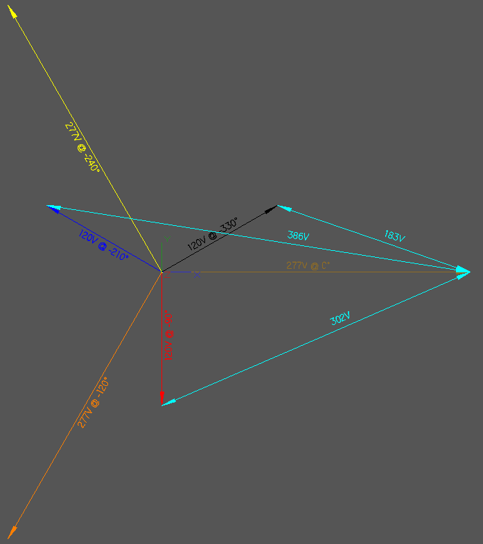
Just out of curiosity, what does the math look like to get the value of 380 volts? I can't seem to figure it out.
 

winnie

Senior Member
Location
Springfield, MA, USA
Occupation
Electric motor research
Bob for the win.

If the 277 and the 120V sources were in phase, then the voltage difference would only be 157V. If nearly in phase (30 degree phase difference expected from a normal 480 to 208/120V transformer) then the voltage could be as low as 183V. Pick other phases, and the voltage could be as high as 385V (or 352V if you don't have 30 degrees between systems).

Given 3 277V phases and 3 120V phases, if you have a 277V device next to a 120V device, and you are not doing anything to specifically control/select for phase angle, then in 6 of the 9 possible situations you will have 380V between devices and a divider would be required. In 3 of the 9 possible situations I don't think the divider is required...but the effort in determining which situation pertains is probably more expensive than just putting in the divider.

(On top of this, do you really want to build a system that depends upon the relative phasing of _different_ circuits from _different_ panelboards, without some way to guarantee that the relative phasing wouldn't change??)

-Jon
 

jtinge

Senior Member
Location
Hampton, VA
Occupation
Sr. Elec. Engr
If both the 120 and 277 are on the same phase I believe the result is under 300 volts.

With typical transformer winding arrangements, how could you have 120V and 277V on the same phase?

Typically, 277V would be derived as the P-N voltage from a 480Y/277V secondary winding, and 120V would be from a 208Y/120V secondary winding (one of several possible configurations). So there would be a phase shift between the 120V and 277V.

The only way I can see 120V and 277V being on the same phase would be if the 120V was tapped from the 277V winding, which I've never seen done.
 

xformer

Senior Member
Location
Dallas, Tx
Occupation
Master Electrician
With typical transformer winding arrangements, how could you have 120V and 277V on the same phase?

Typically, 277V would be derived as the P-N voltage from a 480Y/277V secondary winding, and 120V would be from a 208Y/120V secondary winding (one of several possible configurations). So there would be a phase shift between the 120V and 277V.

The only way I can see 120V and 277V being on the same phase would be if the 120V was tapped from the 277V winding, which I've never seen done.

interesting point... I am curious myself. I know that the words Phase and Time are actually the same thing as they relate to voltage but I was under the impression that the two systems were in synch. Any opinions? :)
 

kwired

Electron manager
Location
NE Nebraska
Can someone include a vector diagram also please?... :)
I will give you a description that will hopefully help you draw your own.

Both the 277 and 120 volt systems will have a common point at the grounded conductor.

Establish that point then draw a line 277 units long. Then draw another line 120 units long from that same point at a 120 angle (the phase angle) If on same phase you will draw the 120 volt line in the same direction as the 277 volt line. The distance between the ends of these two lines (in same units of measurement) will be same as the voltage would be. The same phase application would be simplest to figure out 277-120= 157 volts.

I can see this may be more complicated by wye-wye transformer compared to delta-wye transformer or even a single phase transformer connected to two phase conductors on the primary as compared to connecting it phase to neutral, as the vectors are probably a little more complex to figure out, but hopefully this gives enough understanding to know why the voltages turn out the way they do. Most field electricians would never need to know much more then this on a regular basis.
 
Status
Not open for further replies.
Top