208v to 240v Buck Boost Transformer Calculations

Status
Not open for further replies.

iwire

Moderator
Staff member
Location
Massachusetts
You will believe only after that?:)

I believe if you were to do what mivey suggests in the quote below you will see the mistake you have made.

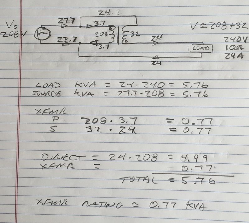
How about you actually draw the circuit, run the calcs, then look at what is actually happening in the windings and see what role the transformer plays in the complete circuit and the actual load in the transformer itself.

Think about what portion the transformer is actually "managing", for lack of a better word
 

mivey

Senior Member
This link to Acmes catalogue discusses the kVA relation in detail:

http://www.delzer.com/powerproducts/ACM_CAT_005_0412/index.html#87

The 1.5 kVA rating is only accurate when connected as an insulation transformer. When installed as an autotransformer the kVA rating is 5-10 X greater and the 1.5 has no relation to the autotransformer any longer, only for naming purposes as Acme brings out.
The transformer load capacity is still 1.5 kVA. What changes is how much of the site load goes through the transformer.

We will somtimes tie down (reduce the step range of) a regulator to increase the size of the load we can let it manage. This does not change the actual transformer loading capacity, just the circuit configuration.

If I have a 167 kVA regulator I can normally manage 1667 kVA. To manage 3333 kVA I can use a 333 kVA regulator or tie a 167 kVA regulator down to a 5% range.
 

Jmays

Member
The transformer load capacity is still 1.5 kVA. What changes is how much of the site load goes through the transformer.

We will somtimes tie down (reduce the step range of) a regulator to increase the size of the load we can let it manage. This does not change the actual transformer loading capacity, just the circuit configuration.

If I have a 167 kVA regulator I can normally manage 1667 kVA. To manage 3333 kVA I can use a 333 kVA regulator or tie a 167 kVA regulator down to a 5% range.


Ah ok, that makes sense.
 

Ingenieur

Senior Member
Location
Earth
An AT is a combination device
electrical and magnetic

208/240 x 11.25 = 9.75 kva is directly thru the windings
32/240 x 11.25 = 1.5 kva tranformer action

partial 'hardwired' + the boost via transformation = 208 + 32 or 1.5 + 9.75
 

Sahib

Senior Member
Location
India
An AT is a combination deviceelectrical and magnetic208/240 x 11.25 = 9.75 kva is directly thru the windings32/240 x 11.25 = 1.5 kva tranformer actionpartial 'hardwired' + the boost via transformation = 208 + 32 or 1.5 + 9.75
So rating of autotransformer=9.75+1.5=11.25 KVA.
 

Ingenieur

Senior Member
Location
Earth
So rating of autotransformer=9.75+1.5=11.25 KVA.

no
they are usually rated on the transformation portion
the transformer wiring polarity determines buck/boost or subtract/add to 'primary' V
although primary/secondary are misnomers in this case

here's another take
100kva load
you need a 15% boost or buck
the AT rating needs to be 15 kva

as others have suggested
draw the diagram
do the math
they are messy devices but that is how I convinced myself that it wasn't fem (freakin' electrical magic) lol
 

iwire

Moderator
Staff member
Location
Massachusetts
they are messy devices but that is how I convinced myself that it wasn't fem (freakin' electrical magic) lol

It sure seemed like magic to me. The first time I purchased and installed buck boosts I ended up calling the sales person and asking if I had the right units for the 3 phase 150 amp circuit.

At this point I have installed a large number of them and am used to the odd ball wire sizes and weird wiring diagrams.
 

Ingenieur

Senior Member
Location
Earth
It sure seemed like magic to me. The first time I purchased and installed buck boosts I ended up calling the sales person and asking if I had the right units for the 3 phase 150 amp circuit.

At this point I have installed a large number of them and am used to the odd ball wire sizes and weird wiring diagrams.

Engineers got it easy
we do it on paper
we can erase our goofups
yours go up in smoke
:)

the tendency is to think about them like a 2 winding device
they are not


those 12/14 are good for 50/40
maybe more in air?
 

iwire

Moderator
Staff member
Location
Massachusetts
Engineers got it easy
we do it on paper
we can erase our goofups
yours go up in smoke
:)

A good buddy of mine was wiring a set of them in a medical research lab we were both working as outside contractors assisting the in house electrician.

The in house guy gave him the transformers and the diagram and my buddy was sure it was wrong. I looked at it and said it looked wrong too me as well. The in house guy said do it.

My buddy is no dummy and he decided to wire them up on table before installing them.

Power on ..... Instant smoke. :D

The supply house provided the wrong diagram and replaced the transformers for free.
 

Ingenieur

Senior Member
Location
Earth
That is just a convention. Its actual rating is 11.25 KVA.

EVERYTHING is 'convention'
lol

if you order a 11.25 kva rated AT it will pass 5-10 times that depending on the buck/boost ratio:happyyes:

depends on size/use
most are rated on the tertiary winding
 
Last edited:

don_resqcapt19

Moderator
Staff member
Location
Illinois
Occupation
retired electrician
Yes But it is necessary to find its maximum rating so that it is not damaged by overload.
And you do that by taking the boost or buck voltage and the load current ....the product of those two is the required VA of the buck boost transformer. You then select a transformer with an equal or higher VA rating.
 

Ingenieur

Senior Member
Location
Earth
Do this
Make a diagram
208 source
208:32 xfmr 2 winding
load of 10 ohm (240 v and 24 a)

Arrange so source + xfmr sec of 32 are additive = 240 across load
tell me what kva the xfmr delivers
I'll post mine after you post yours lol
 

Ingenieur

Senior Member
Location
Earth
Not pretty but the concept is illustrated
ideal xfmr
R load
no phase considered


image_1.jpeg
 
Status
Not open for further replies.
Top