mark32
Senior Member
- Location
- Currently in NJ
Hello again!
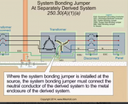
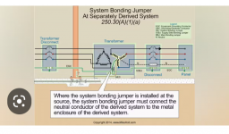
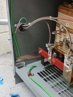
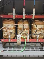
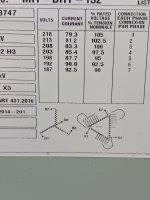
So I snapped a couple of pics from the install yesterday. You may notice I tapped and threaded my own lay in lug in order to land the system bonding jumper, which in turn is bonded to nearby building steel. I do have a question though, according to the tap info on the transformer cover (As shown) I chose to use tap #4 because the equipment is rated for 460v. My math (480 × .975) = 468v sounded pretty good to me. However, once energized, I was getting 485v - 489v across the h1, h2, and h3 terminals. Am I looking at the tap info wrong, should I have gone up to tap #2 instead?? The equipment is not on-site yet, so, there was no load on the transformer.
So I snapped a couple of pics from the install yesterday. You may notice I tapped and threaded my own lay in lug in order to land the system bonding jumper, which in turn is bonded to nearby building steel. I do have a question though, according to the tap info on the transformer cover (As shown) I chose to use tap #4 because the equipment is rated for 460v. My math (480 × .975) = 468v sounded pretty good to me. However, once energized, I was getting 485v - 489v across the h1, h2, and h3 terminals. Am I looking at the tap info wrong, should I have gone up to tap #2 instead?? The equipment is not on-site yet, so, there was no load on the transformer.
")