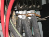
I saw this unusual setup at transmitter site, I was recently at. Seems questionable at best but other than the double lugged wires, and the design consideration of the top breaker spaces being blocked I can't find think of a definitive code violation. That said, the length of the studs looks a little short and there are possible not enough threads engaged. Curious on the forum's thoughts on this, and if it is something that should be corrected.