3 Phase from Single Phase 120/208

CoolWill

Senior Member
Location
Alabama
Occupation
Electrical Contractor
I have a request to supply 3 phase 208Y/120 to a new machine. The location is served by a 200 amp single phase feed supplied from a 208Y/120 volt service at another building further away. Two phases and a neutral on a buried triplex. There is no budget for what it would take to get 3 phase to this building. There is also no getting another machine that will work on single phase. So, I was brought in to figure it out.

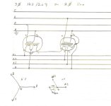
I had the idea that since this feeder is derived from 3 phase that it might be possible to use three suitably selected transformers to do it. In my mind, the phase difference relative to the neutral should make it work. I have attached a quick sharpie drawing of what I have in mind. Will this work?
 

Attachments

  • IMG_20250416_122442370.jpg
    IMG_20250416_122442370.jpg
    1.3 MB · Views: 24
Absolutely not. The closest you could get is an open-delta primary.

May I suggest a VFD instead?
Machine supplier says it won't work nor will a phase converter. I don't know what the machine does but the supplier is adamant that it needs a real 208Y/120.

So let's talk theory. Why won't this work?
 
The basic concept is sound, but the implementation is wrong.

The problem is that the phase angles in your 'delta' are not even. The phase difference across your N terminal is 120 degrees, across your L1 and L2 terminals is 30 degrees. So even though you are using different turns ratios (120:120, 208:120, 120:120) and will get correct 120V L-N, your 'wye' phase angles and L-L voltages will be wrong.

The 'open-delta' that @LarryFine describes is an 'open wye: open delta' connection; you have two 120:208 transformers connected L1-N and L2-N, and the secondaries form two legs of your delta.

Another transformer setup that would work is (I may have the phase dots wrong, but the concept is to use open wye open delta to derive only the 3rd leg):

signal-2025-04-16-135416.jpeg
 
The basic concept is sound, but the implementation is wrong.

The problem is that the phase angles in your 'delta' are not even. The phase difference across your N terminal is 120 degrees, across your L1 and L2 terminals is 30 degrees. So even though you are using different turns ratios (120:120, 208:120, 120:120) and will get correct 120V L-N, your 'wye' phase angles and L-L voltages will be wrong.

The 'open-delta' that @LarryFine describes is an 'open wye: open delta' connection; you have two 120:208 transformers connected L1-N and L2-N, and the secondaries form two legs of your delta.

Another transformer setup that would work is (I may have the phase dots wrong, but the concept is to use open wye open delta to derive only the 3rd leg):

View attachment 2576860
OK. Nice. I knew intuitively there had to be something there by the nature of the 3 phase original source. I've never seen anything like this in the field, so I'm not familiar with it. What, if any, are the drawbacks of this setup? What should be considered when implementing such an animal?
 
You can not use just transformers to create an additional phase. The laws of physics are not just suggestions.
Right, but this isn't "regular" single phase. This may not be the way to go, ultimately, but I do want to understand what is happening there.
 
You can not use just transformers to create an additional phase. The laws of physics are not just suggestions.

You cannot use transformers to create multiple phases from single phase. But if you start with any set of N _different_ phases, you can use transformers to construct a different set of phases.

You can go from 2 phase to 3 (the 'Scott-T connected' transformer) and you can go from 2 out of 3 phases to all 3 (open wye: open delta)
 
OK. Nice. I knew intuitively there had to be something there by the nature of the 3 phase original source. I've never seen anything like this in the field, so I'm not familiar with it. What, if any, are the drawbacks of this setup? What should be considered when implementing such an animal?

The drawbacks are the uneven transformer impedances causing uneven voltage drop under load. In the 'open wye: open delta' the 'open jaw' voltage will be less stable than the other two legs. In the autotransformer setup I described, the derived leg will have poorer voltage stability.

I've not tried calculating how balanced 3 phase loads get reflected on to the 2 phase feeder.

Jonathan
 
Also I've not worked through transformer protection for such a beast, but I think you'd want protective relaying so that if one portion of your transformer bank overloads, you shut down the entire output, rather than leaving your load 'single phased'.
 
Thanks for the lesson. You guys are going to think I'm insane, and maybe that is true, but between me and the machine shop foreman, I think we have a new plan, and cheaper in materials too.

They have a 15 kVA 3 phase diesel genset with a blown engine sitting in the yard. And they have a 10 HP single phase motor on the shelf. Guess what is about to happen?
 
You cannot use transformers to create multiple phases from single phase. But if you start with any set of N _different_ phases, you can use transformers to construct a different set of phases.
The space of voltage vectors is 2 dimensional, so the only two cases are N = 1 (single phase) and N >= 2 (polyphase). Where "different" means "not scalar mutilples of each other," i.e. having a phase difference that is strictly between 0 and 180 degrees.

For the case of the OP, what matters is that it is really a polyphase system, even though L-L-N from a 208Y/120V system is commonly called "single" phase.

Cheers, Wayne
 
They have a 15 kVA 3 phase diesel genset with a blown engine sitting in the yard. And they have a 10 HP single phase motor on the shelf. Guess what is about to happen?
One thing that won't happen is getting 60.0Hz unless the driving motor is synchronous or you add a slight speed increase (~1.04) in the motor-generator connection. And you probably won't get a stable frequency, anyway. Does that matter? Who knows.

You can buy rotary phase converters and it'll be a whole lot easier than monkeying around to build one.... and I'd be skeptical about not the machine working on them. What kind of machine is it, anyway?
 
Thanks for the lesson. You guys are going to think I'm insane, and maybe that is true, but between me and the machine shop foreman, I think we have a new plan, and cheaper in materials too.

They have a 15 kVA 3 phase diesel genset with a blown engine sitting in the yard. And they have a 10 HP single phase motor on the shelf. Guess what is about to happen?
I was just about to suggest a motor/generator set, since the manufacturer does not want a freq drive or rotary converter.
 
One thing that won't happen is getting 60.0Hz unless the driving motor is synchronous or you add a slight speed increase (~1.04) in the motor-generator connection. And you probably won't get a stable frequency, anyway. Does that matter? Who knows.

You can buy rotary phase converters and it'll be a whole lot easier than monkeying around to build one.... and I'd be skeptical about not the machine working on them. What kind of machine is it, anyway?
The machine shop is going to build what ever pulleys we need to get the right speed at the generator head. We only need 3 kVA or less, so I think the 10 HP motor should be able to keep up. I'm not sure what exactly the machine does, but it has 6 drives and all sorts of contractors and relays. It was custom built and the the engineer that came to the site was that there was 208 volts available and just assumed it was three phase.

I talked to the engineering department at the supplier and they claim that they have tried both static and rotary converters and the voltage on the derived leg causes trouble. So they will not warrant their machine fed by one. This has the penny pinchers in the office spooked. As of now, the machine shop is going to fabricate a frame to mount the motor and generator head to. We're going to put it in the compressor room and I'm going to feed it with 208 single phase and take the output to a 30 amp 3 pole disconnect and treat it like as a separately derived system, because it is.
 
The basic concept is sound, but the implementation is wrong.

The problem is that the phase angles in your 'delta' are not even. The phase difference across your N terminal is 120 degrees, across your L1 and L2 terminals is 30 degrees. So even though you are using different turns ratios (120:120, 208:120, 120:120) and will get correct 120V L-N, your 'wye' phase angles and L-L voltages will be wrong.

The 'open-delta' that @LarryFine describes is an 'open wye: open delta' connection; you have two 120:208 transformers connected L1-N and L2-N, and the secondaries form two legs of your delta.

Another transformer setup that would work is (I may have the phase dots wrong, but the concept is to use open wye open delta to derive only the 3rd leg):

View attachment 2576860
That's similar if not exactly like mine.
 

Attachments

  • IMG_5594.jpeg
    IMG_5594.jpeg
    447 KB · Views: 10
Top