Primary transformer resistance

Jpflex

Electrician big leagues
Location
Victorville
Occupation
Electrician commercial and residential
Within a PV fied inverter i found 0.2 ohms between 3/3 phases A,B,C from individual inverter ac output buss.

The output buss start at open contactors and individual fuses, so anything upstream is not relevant.

Then each 3/3 bus teeminate to the primary of an MV 3630 kva Y Delta transformer without any primary disconnect to sepporate the buss from transformer primary windings

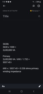
I initially thought an impedance of 0.2 ohms was too low or may indicate a short eithin busses but when i did the math, this value corresponded to my meter reading of 0.2 ohms.

Does seem correct?

3,630 KVa transformer
Primary voltage 690
3 phase

See math computations in pic. Thanks
 

Attachments

  • Screenshot_20250529_190702_Notein.jpg
    Screenshot_20250529_190702_Notein.jpg
    184.8 KB · Views: 11
It's normal for the DC resistance to measure much lower than the AC impedance.
I think you said this in reverse since ac has CEMF and counter self inductance opposition to cutrent flow.

Dcrequires more resistance than ac
 
I think you said this in reverse since ac has CEMF and counter self inductance opposition to cutrent flow.

Dcrequires more resistance than ac
As CoolWill said, LarryFine is correct. The DC resistance is always there and the AC reactance adds to it to make the total AC impedance.
 
As CoolWill said, LarryFine is correct. The DC resistance is always there and the AC reactance adds to it to make the total AC impedance.
I have to disagree. Dc has no reactance only resistance and so this is majority of opposition to current flow. A higher resistance is needed for dc

In an ac circuit there is less resistance needed because reactance is present acting as an additional current opposition though the reversing of current causing a self induced voltage that will oppose a change in current
Right. The DC resistance is low because the reactance is high. Transformers aren't used on DC.
 
I have to disagree. Dc has no reactance only resistance and so this is majority of opposition to current flow. A higher resistance is needed for dc

In an ac circuit there is less resistance needed because reactance is present acting as an additional current opposition though the reversing of current causing a self induced voltage that will oppose a change in current
I don't think we are talking about the same thing; if you apply a DC voltage across the terminals of an inductor and calculate the resistance with Ohm's Law (which is what a DVM does) you will get the DC resistance. If you apply an AC voltage to the same inductor and run the calculation again it will be higher (how much higher depends on the frequency of the AC and the inductance of the inductor) because the impedance thus derived will be higher; the inductor's reactance adds to the DC resistance, which is there independent of the AC frequency, so the impedance will never be less than the DC resistance.

You can model a real inductor by considering it to be a resistor and an ideal inductor in series; for frequency = 0 (DC) the impedance of the model will simply be the resistance of the resistor because the inductor is a short to DC. As you increase the frequency the inductor will start to impede the current and add its impedance to the DC resistance. The impedance of the inductor can be zero, i.e., for DC, but it cannot be negative.

I don't know what you mean by "there is less resistance needed". Needed by what?
 
Last edited:
  • Like
Reactions: J2H
Dcrequires more resistance than ac
I have to disagree. Dc has no reactance only resistance and so this is majority of opposition to current flow. A higher resistance is needed for dc

In an ac circuit there is less resistance needed because reactance is present acting as an additional current opposition though the reversing of current causing a self induced voltage that will oppose a change in current
I am talking about the difference between AC vs DC through a given (inductive) load.

You are talking about using different loads in the attempt to maintain a given current.
 
I am talking about the difference between AC vs DC through a given (inductive) load.

You are talking about using different loads in the attempt to maintain a given current.
Well no i was trying to figure is a measurement of 0.2 phms was acceptable betweem 3 pjase busses

I figured dividing primary transformer voñtage by max amperes x 1.732 to get P windong impedance
 
I don't know what you mean by "there is less resistance needed". Needed by what?
What i mean is that for example a reactor being a coil of wire within preferably an iron core will need less resistance in series with this reactive coil for AC voltage/ current rather than DC applied due to the effect of CEMF which is the same thing you explained in the application of frequency without damaging the inductor coil
 
Actually i was not looking into loads because my concern was whether a short existed between Y primary leads to the transformer.

The company does not want to use meggars so i tested between 2 phase leg busses on my Dvom volt meter on all scales including 200k ohm.

My reading seemed low at 0.2 ohms. I did not know whether this was acceptable values and aware that this is not a complete test.

The math i did came up at 0.2 ohms of impedance for max primary current to make me belive a short may not exist?

The coils within the primarty should be reactive which also complicates this because the dvom is not testing impedance from an AC source
 
I don’t think you can get an accurate measurement with a DVOM for seeing if there is a short within the coils of a AC motor/transformor/ect

Only thing you could check from is phase to ground.
 
I don’t think you can get an accurate measurement with a DVOM for seeing if there is a short within the coils of a AC motor/transformor/ect

Only thing you could check from is phase to ground.
I did check phase to ground and inverter metal chassis. This was ok with OL.

how could you check for shorted windings prior to start up? If a coil shorts to adjacent coil it will mess up the Primary secondary ratio output etc
 
If each coil isolated from the others has the same identical DC resistance I would think they would all be good. Someone else will know more hopefully as to the correct way.
 
If each coil isolated from the others has the same identical DC resistance I would think they would all be good. Someone else will know more hopefully as to the correct way.
There isnt much resistance to check in this situation unfornunately. It is mostly inductive reactance in effect but you need current flowing and a frequency of current for this.

The impedance is simply the total resistance and inductive reactance of a circuit

Test can be done with circuit energized but this defeats the purpose of testing prior to start up and avoid short circuit explosions
 
You could connect an incandescent light bulb in series with the primary. This would act as a current limiter if the coil is shorted. You can measure the total current and the voltage drop across the light bulb and across the coil and determine the (rough) impedance of the coil from that.
 
I am talking about the difference between AC vs DC through a given (inductive) load.

You are talking about using different loads in the attempt to maintain a given current.

This is exactly the misunderstanding.

The original calculation gave the 60 Hz fully loaded impedance of the transformer. Not the DC impedance.

You would want to calculate the unloaded impedance (from the magnetizing current), and I'd expect the DC impedance to be much lower than the unloaded impedance.

I'd also expect the DC impedance to be much lower from a loss dissipation perspective. 3000A through 0.2 Ohms is quite a bit of heating.

A DVM is not suitable for measuring the low DC impedance of a large transformer. You need a specialized microohm meter.

Jonathan
 
You would want to calculate the unloaded impedance (from the magnetizing current), and I'd expect the DC impedance to be much lower than the unloaded impedance.


Jonathan
These inverters supply power to the grid so yes the current and heat will be high.

However, it seems i would need to place an ammeter around the primary and calculate the impedance based on actual current reading

with the impedance value i could further calculate the primary henry value based on

2x pie x frequency x L Henry = XL inducgive reactance impendance
 
Top