Is it correct for the engineer to ask for another ground rod on the transformer?

Charlypt

Member
Location
Florida
Occupation
Electrician
We have this project.
1. Existing 277/480V 3-phase pad mounted utility company transformer.
2. CT Meter, located close to utility transformer.
3. ECB 450A 480V, 2-Pole
5. Panel 1000A, MCB, 120/240V, 1-Phase, 3 Wire

T1: Dry Type Transformer 480V to 120/240V, 1-Phase, 3 Wire
Primary Feeder: 2 Sets (2) #4/0, #2 EG
Secondary Feeder: 3 Sets (3) #400, #3/0 EG
ECB and Panel located beside the transformer T1, at 200 ft from utility transformer.


1751982971298.png
And this is the ground/bonding connection that the installer made.

1752005623958.png

I'd appreciate it if anyone could spot any problems with the installation.
If it's correct, why is a second ground electrode necessary on the transformer?

Thank you in advance.
 
T1: Dry Type Transformer 480V to 120/240V, 1-Phase, 3 Wire
Primary Feeder: 2 Sets (2) #4/0, #2 EG
Secondary Feeder: 3 Sets (3) #400, #3/0 EG
ECB and Panel located beside the transformer T1, at 200 ft from utility transformer.
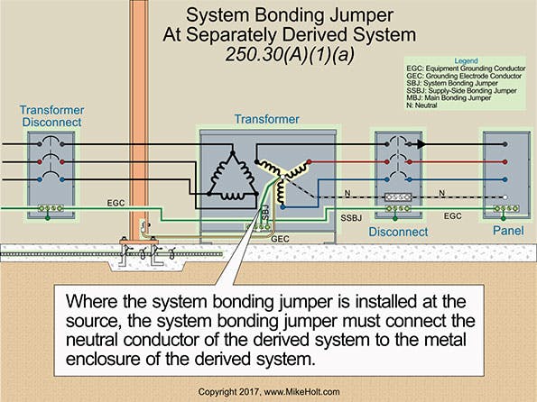
This is all on the load side of the service disconnect so the NEC applies. The #3/0 EG's are actually SSBJ's not EGC's and are larger than required but that's fine. There is nothing that would prohibit a bonding connection between the raceways exiting the panel and the service disconnect although it's not required. The T1 transformer GEC is required to be connected the GES if this is considered a single structure.
 
he #3/0 EG's are actually SSBJ's not EGC's and are larger than required but that's fine.
I agree, we don't use EG on the conduits going to the panel. 3 Sets (3) #400, #3/0 EG are the textual specifications.

Regarding the bonding jumper, correct my calculation if I'm wrong:
3 * 400 kcmil = 1200 kcmil.
250.102(C)(1) for conductors over 1100 kcmil, the bonding jumper would be 12.5% of the total area of the conductors.
1200 * 0.125 = 150 kcmil.
According to Table 8 - Chapter 9
150 kcmil would be greater than 2/0 (133.1) and less than 3/0 (167.8).
So, 3/0 was selected as the size for the bonding jumper.
Yes these are supply side bonding jumpers. SSBJ's are sized according the conductors in each raceway not the total CM of all of the parallel raceways. So for 400 kcmil each raceway would require a SSBJ with a minimum size of #1/0 from Table 250.102(C)(1). Your calculation would be used to size the system bonding jumper.
 
So a SSBJ is required in each raceway. Why aren't they shown on your drawing?
The installer didn't install them because he says that since a ground has already been run from the service and everything is interconnected, he doesn't see the need for it. I don't like it, and it's the first time I've seen something like this, but it's already been done. I'm not sure if there's any NEC violation, hence my question.
 
I'm not sure if there's any NEC violation, hence my question.
The SSBJ in each raceway is required similar to this.
ecmweb_com_sites_ecmweb.com_files_uploads_2015_12_Grounding_and_bonding_3.png
 
Check the second part of the example: Single supply-side bonding jumper.

1752070887715.png

Also
250.102(C)

1752070832677.png

Table 250.102(C)(1)

1752071060826.png
 

Attachments

  • 1752070991057.png
    1752070991057.png
    10.8 KB · Views: 0
  • 1752071045355.png
    1752071045355.png
    10.8 KB · Views: 0
is the first drawing what the contractor was given or were the details with grounding and bonding spelled out? it s been awhile but seems like more detail would have been given. I'm not busting balls...just asking.
 
What I understand is that you can install multiple SSBJ (one per pipe) or a single SSBJ
Each raceway requires a SSBJ. If you had parallel conductors in a single raceway like a wireway then you would use the calculation to determine the single SSBJ size.
 
Each raceway requires a SSBJ. If you had parallel conductors in a single raceway like a wireway then you would use the calculation to determine the single SSBJ size.
This never mentions parallel conductors in a single raceway; it mentions parallel conductors in two or more raceways.
The 2023 NEC is even more specific, separating the two cases: multiple and single SSBJ.

1752073029271.png
 
is the first drawing what the contractor was given or were the details with grounding and bonding spelled out? it s been awhile but seems like more detail would have been given. I'm not busting balls...just asking.
The contractor received the first drawing, the second shows how the grounding system was installed.
 
This never mentions parallel conductors in a single raceway; it mentions parallel conductors in two or more raceways.
You're not installing a single SSBJ you need to install one in each raceway. I don't have access to my codebook right now but I can provide the section later.
 
Top