GEC through bonding bushings

BackCountry

Electrician
Location
Southern California
Occupation
Licensed Electrician and General Contractor
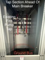
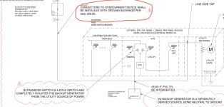
I have a 800A line side tap fused disconnect on a 1600a 3p 480v service. My line side conductors are 3 parallel runs of 400kcmil aluminum with a 4/0 aluminum GEC. I have bonding bushings on 3” EMT on both sides coming from the fused disconnect into the tap section of the switch gear ahead of the building main disconnect.

My question is: I believe I have to wrangle the GEC through the bonding bushings on both sides, which with 4/0 is going to be pretty challenging. I’d rather use a bonding jumper, but my interpretation of 250.102(C)(1) is that the bonding jumper to the bonding bushings would still need to be 4/0 because my ungrounded conductors are 400’s x 3 = 4/0 because that lands between 900 and 1750 in the aluminum column.

Am I seeing that right? All of my 3” bonding bushings max out at 1/0 with the lay in lug included, so I’ll need to order lay in lugs that can even handle 4/0.
 
Why are you running a GEC with the circuit conductors? Is there not a GEC already in the switch gear? If it's not in a good place, why not run the GEC directly to the electrode(s)?

Also the service is wye? Please clarify.

Do a careful read of 250.64(D) and 250.24, particularly (C).

This also gets into questions about grounding and bonding PV supply side connections, which in the past were pretty ambiguous in the code. But nowadays treating your new disco like a new service disconnect is the surest way to go.
I’m running a neutral and ground into the disconnect and leaving the neutral behind because I don’t need it, so I’m bonding the neutral and ground in the fused disconnect. Since the neutral has to at least be the size of the grounding conductor, they’re both 4/0. I’m running the ground from the fused disconnect with the three parallel runs, and hitting the ground bus in the switch gear.
 
I’m talking about between the fused disconnect and the switch gear, so this isn’t an EGC.
Well it doesn't sound like a GEC under that description either. A GEC goes to an electrode.
I’m running a neutral and ground into the disconnect and leaving the neutral behind because I don’t need it, so I’m bonding the neutral and ground in the fused disconnect. Since the neutral has to at least be the size of the grounding conductor, they’re both 4/0. I’m running the ground from the fused disconnect with the three parallel runs, and hitting the ground bus in the switch gear.
Why are you running both a neutral and ground if you're bonding them together in the disconnect? You're probably creating an objectionable current situation. Need more detail about where those would land at the switch gear end, where/how the service is presently grounded, bonded, etc. But running both green and white on the supply side of a service disco is usually not right.

You may or may not need to land your neutral (or a bonding jumper) in a grounding bushing depending on the methods you use, but see 250.92. And it wouldn't need to be on both ends.
 
I’m talking about between the fused disconnect and the switch gear, so this isn’t an EGC.
By definition a GEC connects to an electrode.

There is a GEC to the switchgear and there needs to be a GEC from the fused disconnect to an electrode (either the same one as the one connected to the switchgear or another one bonded to it) but no grounding conductor should be run with the conductors between them.
 
...There is a GEC to the switchgear and there needs to be a GEC from the fused disconnect to an electrode (either the same one as the one connected to the switchgear or another one bonded to it) but no grounding conductor should be run with the conductors between them.

If the existing GEC fits the 'common location' requirement in 250.64(D)(3) then no new GEC from the disco should be required.
 
If the existing GEC fits the 'common location' requirement in 250.64(D)(3) then no new GEC from the disco should be required.
There may be more than one way to ground a supply side connected PV system, but the way I described is the one I always use.
 
If the existing GEC fits the 'common location' requirement in 250.64(D)(3) then no new GEC from the disco should be required.
So if you had a gutter on the utility side of the existing service disconnect, and in the gutter you tap all the service conductors for the new service disconnect, and the GEC connects to the grounded service conductor within this gutter, that would count as a "common location".

Now suppose you get rid of the gutter but do the exact same thing within the enclosure of the existing service disconnect. The grounded conductor from the utility, the grounded conductor going to the new service disconnect, and the GEC all land on the same terminal bar. Does this still count as a "common location"?

[Note that I'm not familiar with the geometry of switchgear, if they have separate sections then perhaps in applying the above to switchgear you'd treat each section as a separate enclosure.]

Cheers, Wayne
 
I’m talking about between the fused disconnect and the switch gear, so this isn’t an EGC.
For a line side tap, there is no EGC or GEC run from the tap location to the disconnect. That disconnect is a service disconnect and has a main bonding jumper and a GEC connection just like any other service disconnect.
 
...

Now suppose you get rid of the gutter but do the exact same thing within the enclosure of the existing service disconnect. The grounded conductor from the utility, the grounded conductor going to the new service disconnect, and the GEC all land on the same terminal bar. Does this still count as a "common location"?
I say yes. As with the trough scenario, your GEC termination isn't on the load side of the enclosure that contains the tap. All the service entrance conductors are common to that location.

[Note that I'm not familiar with the geometry of switchgear, if they have separate sections then perhaps in applying the above to switchgear you'd treat each section as a separate enclosure.]

Agree. If the GEC termination is in the section with the service disconnect(s) or any section that might be on the supply side, that'd be a common location.
 
Your gec does not have to be ran in the same conduit as your SECs

You can run your GEC bare supported to building structure or in PVC therefore no bonding required. Unless you have a spec that says otherwise.

Sent from my SM-S926U using Tapatalk
 
For a line side tap, there is no EGC or GEC run from the tap location to the disconnect. That disconnect is a service disconnect and has a main bonding jumper and a GEC connection just like any other service disconnect.
I would agree; however, the EE is showing a ground conductor running from the ground bus in the switch gear (which crosses all sections at the bottom) to the fused line side tap disconnect. I called him to confirm and he said that it was required as an EGC. That’s where I got confused because I thought of it more like a GEC, tying in to the grounding electrode (in this case, the ground bus of the switch gear).

If I don’t need it at all, I could of course run the neutral back to the tap (see photo, the existing fire pump tap does not even bring the neutral into the disconnect).

This is always confusing to me.
 

Attachments

  • 019ab2e9-0352-7bbd-86cc-4eda76f5217f.jpeg
    019ab2e9-0352-7bbd-86cc-4eda76f5217f.jpeg
    438.9 KB · Views: 5
I would agree; however, the EE is showing a ground conductor running from the ground bus in the switch gear (which crosses all sections at the bottom) to the fused line side tap disconnect. I called him to confirm and he said that it was required as an EGC. That’s where I got confused because I thought of it more like a GEC, tying in to the grounding electrode (in this case, the ground bus of the switch gear).

If I don’t need it at all, I could of course run the neutral back to the tap (see photo, the existing fire pump tap does not even bring the neutral into the disconnect).

This is always confusing to me.
Then the EE does not understand what a line side tap really is. It is nothing more than service conductors run to a service disconnect and there is no EGC or GEC run with service conductors. The disconnect at the load end of the line side tap conductors must have the grounded conductor extended to it.

The existing fire pump is a violation as the fire pump controller is a service disconnect and the grounded conductor must be extended to all service disconnects.
 
I would agree; however, the EE is showing a ground conductor running from the ground bus in the switch gear (which crosses all sections at the bottom) to the fused line side tap disconnect. I called him to confirm and he said that it was required as an EGC. That’s where I got confused because I thought of it more like a GEC, tying in to the grounding electrode (in this case, the ground bus of the switch gear).

If I don’t need it at all, I could of course run the neutral back to the tap (see photo, the existing fire pump tap does not even bring the neutral into the disconnect).

This is always confusing to

Then the EE does not understand what a line side tap really is. It is nothing more than service conductors run to a service disconnect and there is no EGC or GEC run with service conductors. The disconnect at the load end of the line side tap conductors must have the grounded conductor extended to it.

The existing fire pump is a violation as the fire pump controller is a service disconnect and the grounded conductor must be extended to all service disconnects.
Right, I always run a neutral to the service disconnect, bond there, and then the EGC terminates to that bonded neutral and ground bus.

Here’s what the SLD shows (see photo). Plans examiner made me add the bonding bushing to the line side tap fused disconnect conduit between the switch gear and the disconnect. That’s why this is all so confusing, I can happily run a bonding jumper from the disconnect ground bus, but does that also need to be 4/0 if my three parallel runs are 400’s.
 

Attachments

  • IMG_0420.jpeg
    IMG_0420.jpeg
    371.5 KB · Views: 7
Right, I always run a neutral to the service disconnect, bond there, and then the EGC terminates to that bonded neutral and ground bus.

Here’s what the SLD shows (see photo). Plans examiner made me add the bonding bushing to the line side tap fused disconnect conduit between the switch gear and the disconnect. That’s why this is all so confusing, I can happily run a bonding jumper from the disconnect ground bus, but does that also need to be 4/0 if my three parallel runs are 400’s.
The conduit needs to be bonded but only at one end, IMO.
 
Top