There's a whole working group on this issue you can join.
Send me a PM if you're interested in checking that out.
---
All these topics are active discussion, and there is a lot of regulatory and advocacy work on this topic now. Recent press:
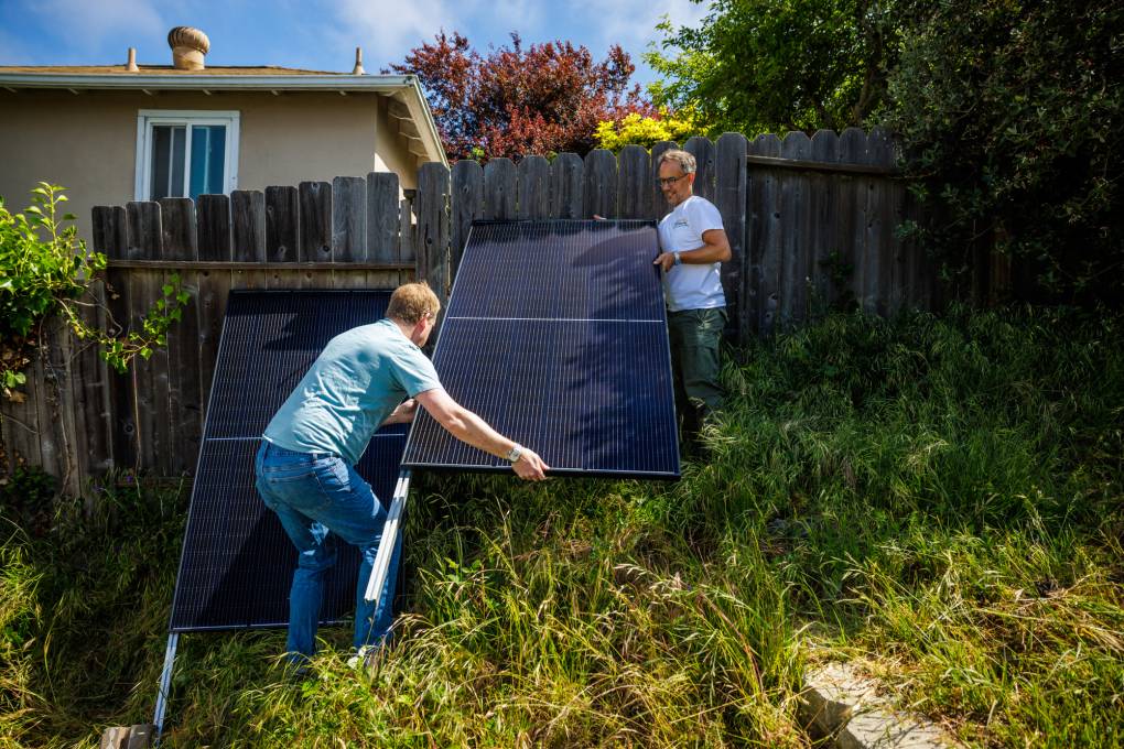
A movement is growing to bring small, portable, affordable solar to a balcony or backyard near you. But before you see them everywhere, advocates must break through significant barriers.

www.kqed.org
On the GFCI the issue is that some legacy GFCI products measure current with current transformers, and the designers never considered that power might flow backwards through the wires. CT's are directional, and this means negative current perhaps at a 50:1 or whatever ratio flows into the measuring circuit. The claim is that this negative current can fry the GFCI and/or render the
Breaker masking is a greater theoretical concern, which is more tangled.
----
Millions of these units are in use in Europe where it's been accepted at all levels from the power companies, to regulators to the checkout gal at Ikea.
That's called "breaker masking" in the world of plug in solar.