I know I've read you saying so in other posts, but could you please remind me how it does not apply to any other load-side-of-service-disconnecting-means conductors, be they wire or busbar?To be clear, that's only true under the 2011 code or earlier. In 2014 and 2017 the rule only applies to a panelboard.
You are using an out of date browser. It may not display this or other websites correctly.
You should upgrade or use an alternative browser.
You should upgrade or use an alternative browser.
120% rule
- Thread starter eds
- Start date

- Status
- Not open for further replies.
PVfarmer
Senior Member
- Location
- Newport County, Rhode Island, USA
To be clear, that's only true under the 2011 code or earlier. In 2014 and 2017 the rule only applies to a panelboard.
Wait...are you saying under 2011, the 120% applies to the blue text AND red conductors, but doesn't for 2014 and 2017?
I'm saying (I think) if there's no 160A breaker here below, so the 200A breaker is connected to lugs of a panel, a 200A rated panel is no good, you'd need a 400A rated panel and 280A conductors no matter what year.
With 200A and 160A breakers, 120% applies to the panel (160A + 80A = 240, also 200A *120 = 240A), but 200A applies to conductors between the 200A and 160A.
METER
|
|
200A service breaker
|
|
200A rated panel with 160A main breaker
|
|----->160A of load
|
}<-- 80A PV
Conductors have 200A source at service end and 80A PV source at the other. A 100A conductor is not enough under any interconnect-sources requirement.Right, I agree- the conductors in red, even though there will only be 100A of load, are still "exposed" to the 200A breaker is what you're saying?
If it goes 200A breaker --> main lugs, OR if it goes 200A --> 100A breaker, 100A is not enough for those conductors.
I understand the barn panel to be 200A MLO field adapted to MCB via backfed 100A breaker with MAIN kit installed.BUT, if they go 200A breaker to main lugs, the 200A rated panel is not enough, period, because those conductors and the main lug panel bus are exposed to 280A.
The confusing part is- it can't be a "MLO" panel as in "Only", as in the lugs are connected to the 200A breaker(by the conductors of course)... main lug OUT for the 100A, ok. There has to be a 100A breaker (or up to 160A with the 80A of PV) between the 200A breaker and the 200A rated bus for that bus to be ok.
PVfarmer
Senior Member
- Location
- Newport County, Rhode Island, USA
1. A 100A conductor is not enough under any interconnect-sources requirement.
I understand the barn panel to be 200A MLO field adapted to MCB via backfed 100A breaker with MAIN kit installed.
1. Right, because even if you had a 100A main service breaker, 100A + 80A = 180A.
2. Same here, in which case we (mostly you, the expert) are saying the 120% rule applies to said panel, and the panel is ok, whereas the conductors between the 200A breaker and 100A breaker must be sized to... 280A?
The inverter output connection (the 80A breaker) is being made through the 100A breaker in barn panel- however, since the OCD protecting the feeders is 200A, the taps shall be sized to 280A.
So is that a long run?
If so, couldn't you substitute a 100A breaker for the 200A service breaker, and size to 180A?
(2) Taps. In systems where inverter output connections are
made at feeders, any taps shall be sized based on the
sum of 125 percent of the inverter(s) output circuit
current and the rating of the overcurrent device protecting
the feeder conductors as calculated in 240.21(B).
jaggedben
Senior Member
- Location
- Northern California
- Occupation
- Solar and Energy Storage Installer
I know I've read you saying so in other posts, but could you please remind me how it does not apply to any other load-side-of-service-disconnecting-means conductors, be they wire or busbar?
In 2011, 705.12(D)(2) said that a 'busbar or conductor' could be loaded up to 120% of its rating. No guidance on same end or opposite end, taps, or any other specific situations, just a blanket rule.
That section and its language is entirely gone in 2014 and subsequently.
What still exists is a version of the old 705.12(D)(7), which was specific to panelboards and specified the opposite end rule for above 100% up to 120%. This section is 705.12(D)(2)(3)(b) in 2014 and 705.12(B)(2)(3)(b) in 2017. It refers specifically only to panelboards and is a subsection of a section that refers specifically only to busbars in panelboards.
Feeders now have their own section (705.12(B)(1) in 2017) which does not contain any mention of 120% as a number. The rules for feeders now amount to 100% if fed by two sources that can add together (e.g. tap to a source). Implicitly, if the feeder is fed from opposite ends, then the interactive source can be as high as the rating of the feeder.
Okay... perhaps I'll remember the next time it comes up. :blink:In 2011, 705.12(D)(2) said that a 'busbar or conductor' could be loaded up to 120% of its rating. No guidance on same end or opposite end, taps, or any other specific situations, just a blanket rule.
That section and its language is entirely gone in 2014 and subsequently.
What still exists is a version of the old 705.12(D)(7), which was specific to panelboards and specified the opposite end rule for above 100% up to 120%. This section is 705.12(D)(2)(3)(b) in 2014 and 705.12(B)(2)(3)(b) in 2017. It refers specifically only to panelboards and is a subsection of a section that refers specifically only to busbars in panelboards.
Feeders now have their own section (705.12(B)(1) in 2017) which does not contain any mention of 120% as a number. The rules for feeders now amount to 100% if fed by two sources that can add together (e.g. tap to a source). Implicitly, if the feeder is fed from opposite ends, then the interactive source can be as high as the rating of the feeder.
280A would certainly work. I'm truly perplexed to say what 705.12(D)(2)(1) and (2)(2) entail in this regard. What is a [feeder] tap to a conductor supplied from both ends?...
2. Same here, in which case we (mostly you, the expert) are saying the 120% rule applies to said panel, and the panel is ok, whereas the conductors between the 200A breaker and 100A breaker must be sized to... 280A?
The inverter output connection (the 80A breaker) is being made through the 100A breaker in barn panel- however, since the OCD protecting the feeders is 200A, the taps shall be sized to 280A.
So is that a long run?
If so, couldn't you substitute a 100A breaker for the 200A service breaker, and size to 180A?
(2) Taps. In systems where inverter output connections are
made at feeders, any taps shall be sized based on the
sum of 125 percent of the inverter(s) output circuit
current and the rating of the overcurrent device protecting
the feeder conductors as calculated in 240.21(B).
So I have seen all the replies, and I appreciate them. I have quickly read thru them and hope to shed some light on my situation, and I do have a previous thread about this same job, but every time I think it's clear I run into another question. Here is the set up
Meter
200 breaker disconnect (ecc 225 with a ccv2200 all cutler hammer, no bussing just lugs on breaker)
Gutter
3" conduit to barn 200' away
200 main lug panel with a 100 amp back fed breaker with hold down
80 pv breaker located at bottom right of panel, 100 at top left
2 things confused on, one conductor size if I must size at 100 amp and 125% of inverter out put then wire is to big for breaker either copper or al
Second I am utilizing the tap rule off of 200 service disconnect, 100 to barn and 100 to the house, I don't believe the 100 tap to the house affects any thing on the solar calculations.
Again thanks for the patience and the knowledge
PVfarmer
Senior Member
- Location
- Newport County, Rhode Island, USA
What is a [feeder] tap to a conductor supplied from both ends?
:thumbsup: It's a load side PV connection in the barn, but really it's supply side because it's connected to the 200A breaker lugs...?
I mean...there are barn loads, but there are also house loads.
I think the main breaker in the house is the "service", and the PV is connected supply side. So...?
Meter
200 breaker disconnect (ecc 225 with a ccv2200 all cutler hammer, no bussing just lugs on breaker)
Gutter
3" conduit to barn 200' away
200 main lug panel with a 100 amp back fed breaker with hold down
80 pv breaker located at bottom right of panel, 100 at top left
2 things confused on, one
1 conductor size if I must size at 100 amp and 125% of inverter out put then wire is to big for breaker either copper or al
2 Second I am utilizing the tap rule off of 200 service disconnect, 100 to barn and 100 to the house, I don't believe the 100 tap to the house affects any thing on the solar calculations.
1
Hold on, isn't there something missing here....a switch?
---
Meter
200 breaker disconnect
Gutter
PV disconnect switch!
3" conduit to barn 200' away
---
If you had a 125A switch "adjacent" to the meter, wouldn't it be... a "service disconnect" of some sort? Then you could use smaller gauge conductors (and smaller condiut) for the 200 feet...1 AWG, I think?
I'm pretty sure 1 AWG would fit the 100A breaker in the barn panel?
I thought a PV disco switch right by the meter was required...
2- I can't help you there with much confidence.
")
ggunn
PE (Electrical), NABCEP certified
- Location
- Austin, TX, USA
- Occupation
- Consulting Electrical Engineer - Photovoltaic Systems
:thumbsup: It's a load side PV connection in the barn, but really it's supply side because it's connected to the 200A breaker lugs...?
I mean...there are barn loads, but there are also house loads.
I think the main breaker in the house is the "service", and the PV is connected supply side. So...?
No. A supply side connection means a connection to the service outside the first OCPD. If it's behind any OCPD, it's a load side connection. There is no such thing as a "service"; it's either a service or it's not.
PVfarmer
Senior Member
- Location
- Newport County, Rhode Island, USA
just a thought
just a thought
Not sure if anyone's mentioned this, but...
You have 15kW of PV going through 200 feet of conduit. So 62.5 amps max.
I'm getting voltage drop of 3.2% using 4 AWG for 62.5A over 200 feet. (240 "single phase")
And depending on loads in the barn...
2.6% for 80A with 2 AWG and 3.3% for 100A/2 AWG.
jaggedben
Senior Member
- Location
- Northern California
- Occupation
- Solar and Energy Storage Installer
So I have seen all the replies, and I appreciate them. I have quickly read thru them and hope to shed some light on my situation, and I do have a previous thread about this same job, but every time I think it's clear I run into another question. Here is the set up
Meter
200 breaker disconnect (ecc 225 with a ccv2200 all cutler hammer, no bussing just lugs on breaker)
Gutter
3" conduit to barn 200' away
200 main lug panel with a 100 amp back fed breaker with hold down
80 pv breaker located at bottom right of panel, 100 at top left
2 things confused on, one conductor size if I must size at 100 amp and 125% of inverter out put then wire is to big for breaker either copper or al
Second I am utilizing the tap rule off of 200 service disconnect, 100 to barn and 100 to the house, I don't believe the 100 tap to the house affects any thing on the solar calculations.
Again thanks for the patience and the knowledge
Again, having to size the outside tap to 233A is more or less the worst case scenario of AHJ interpretation. It's rather moot what we think: if you really want to be assured of what will be required, then ask your AHJ.
With that said, I'm with PV farmer in not really understanding why you don't put in a smaller overcurrent device, either for the service disconnect or right next to it, if needed to justify smaller conductors to the AHJ.
:thumbsup: It's a load side PV connection in the barn, but really it's supply side because it's connected to the 200A breaker lugs...?
There's two connections in series. The code may not state it explicitly, but when there's connections in series it makes sense to consider them separately each in their own context.
I thought a PV disco switch right by the meter was required...
Often required by utilities, but not by the NEC. Another thing to make sure is okay with the local people who have authority.
PVfarmer
Senior Member
- Location
- Newport County, Rhode Island, USA
If it's behind any OCPD, it's a load side connection.
In that case, everything has to be sized to 280 amps then, including the conductors to the 100A house breaker?
I'd say the PV is for sure connected in relation to the main house breaker on the supply side- of the main house breaker.
ggunn
PE (Electrical), NABCEP certified
- Location
- Austin, TX, USA
- Occupation
- Consulting Electrical Engineer - Photovoltaic Systems
If it's behind any OCPD it's a load side connection. Period. That's what load side means.In that case, everything has to be sized to 280 amps then, including the conductors to the 100A house breaker?
I'd say the PV is for sure connected in relation to the main house breaker on the supply side- of the main house breaker.
Quite frankly, I haven't slogged through all the details of the system enough to state numbers, but when you say "supply side" it means something specific and it is not relative. A connection to a subpanel to a main with OCPD anywhere between it (the sub) and the service conductors is a load side connection, irrespective of which side of the main breaker (if there is one) on the sub you land your conductors.
PVfarmer
Senior Member
- Location
- Newport County, Rhode Island, USA
1 There's two connections in series. The code may not state it explicitly, but when there's connections in series it makes sense to consider them separately each in their own context.
2 Often required by utilities, but not by the NEC. Another thing to make sure is okay with the local people who have authority.
3 With that said, I'm with PV farmer
4 A connection to a subpanel to a main with OCPD anywhere between it (the sub) and the service conductors is a load side connection, irrespective of which side of the main breaker (if there is one) on the sub you land your conductors.
1- Ok, but doesn't it also make sense that...yes, you have 2 sets of conductors, each set going to a 100A breaker, and they will carry at most 100A to loads (or 62.5A of PV the other direction)...but!...there is 200A at the lugs below the 200A breaker.
So while the 200A is splitting in 2 directions, those 100A rated conductors are exposed to 200A at the lugs.
I'd go with 200A rated (for the ~6 feet) between lugs and switch, and lugs/house.
2- If it's the difference between a 200 foot run of 300kcmil or 2AWG... why not exceed the requirements?
3- Hey! That's a good thing.
4- Right. However, the 120% rule has nothing to do with conductors.
The OP's setup is different, because the PV is at the opposite end of the busbar from the 100A breaker in the barn, and also at the opposite end of the feeder from the primary source OCD, but isn't the inverter output connection *also* at the primary source OCD end of the feeder for the house?
(2)(1) "that portion of feeder on the load side of the inverter" is going to the house.
(2)(2) the inverter output connection is also the feeder to the barn, and it's tapped to the house feeder.
(2) Bus or Conductor Ampere Rating.
One hundred twenty-five percent of the inverter output circuit current
shall be used in ampacity calculations for the folIowing:
(1) Feeders. Where the inverter output connection is made
to a feeder at a location other than the opposite end of
the feeder from the primary source overcurrent device,
that portion of the feeder on the load side of the inverter
output connection shall be protected by one of
the following:
(a) The feeder ampacity shall be not less than the sum
of the primary source overcurrent device and
125 percent of the inverter output circuit current.
(b) An overcurrent device on the load side of the inverter
connection shall be rated not greater than the
ampacity of the feeder.
(2) Taps.ln systems where inverter output connections are
made at feeders, any taps shall be sized based on the
sum of 125 percent of the inverter(s) output circuit
current and the rating of the overcurrent device protecting
the feeder conductors as calculated in 240.21 (B).
(3) Busbars. (nothing about conductors)
ggunn
PE (Electrical), NABCEP certified
- Location
- Austin, TX, USA
- Occupation
- Consulting Electrical Engineer - Photovoltaic Systems
1- Ok, but doesn't it also make sense that...yes, you have 2 sets of conductors, each set going to a 100A breaker, and they will carry at most 100A to loads (or 62.5A of PV the other direction)...but!...there is 200A at the lugs below the 200A breaker.
So while the 200A is splitting in 2 directions, those 100A rated conductors are exposed to 200A at the lugs.
I'd go with 200A rated (for the ~6 feet) between lugs and switch, and lugs/house...
Sorry, I'm not slogging through all that. You do see that if you have 100A of OCPD from the utility on one end of a feeder and an 80A breaker from the inverter on the other, and there are no tapped loads in between them, even fully loaded the net current through the feeder can never be more than 100A and could be as low as 20A, right? Just checking. This stuff is really pretty simple.
With no loads between breakers and the system operating under nominal conditions, as high as 80A PV to utility. As low as 0A when dark.Sorry, I'm not slogging through all that. You do see that if you have 100A of OCPD from the utility on one end of a feeder and an 80A breaker from the inverter on the other, and there are no tapped loads in between them, even fully loaded the net current through the feeder can never be more than 100A and could be as low as 20A, right? Just checking. This stuff is really pretty simple.
My "unanswered" question in this thread is"
What is Article 705 taps? Tap is defined in and for Article 240, but not in or for Article 705. If taps...
shall be sized based on the
sum of 125 percent of the inverter(s) output circuit
current and the rating of the overcurrent device protecting
the feeder conductors as calculated in 240.21(B)
...wouldn't that yield a conductor larger than is normally protected by the feeder supply OCPD as defined in Article 240 and therefore nullify it as a tap???SolarPro
Senior Member
- Location
- Austin, TX
With no loads between breakers and the system operating under nominal conditions, as high as 80A PV to utility. As low as 0A when dark.
My "unanswered" question in this thread is"
What is Article 705 taps? Tap is defined in and for Article 240, but not in or for Article 705. If taps...shall be sized based on thesum of 125 percent of the inverter(s) output circuitcurrent and the rating of the overcurrent device protectingthe feeder conductors as calculated in 240.21(B)...wouldn't that yield a conductor larger than is normally protected by the feeder supply OCPD as defined in Article 240 and therefore nullify it as a tap???
No. Applying the tap rule as described above, the formula would look like this (assuming a tap less than 25'):
Load Tap Ampacity ≥ (Supply OCPD + (Inverter Current x 125%)) x 33%
See: Interactive Inverter Interconnections
Attachments
Load tap ampacity... so the conductor (feeder tap) to the right of the blue line? What about the inverter "tap" ampacity... or is that what you are attempting to depict?No. Applying the tap rule as described above, the formula would look like this (assuming a tap less than 25'):
Load Tap Ampacity ≥ (Supply OCPD + (Inverter Current x 125%)) x 33%
See: Interactive Inverter Interconnections
I suppose I should read the linked article. Maybe later...
PVfarmer
Senior Member
- Location
- Newport County, Rhode Island, USA
You do see that if you have 100A of OCPD from the utility on one end of a feeder and an 80A breaker from the inverter on the other, and there are no tapped loads in between them, even fully loaded the net current through the feeder can never be more than 100A and could be as low as 20A, right?
But that isn't it- there's a 200A breaker on one end of the feeder, and either the 100A subpanel breaker or the 80A PV breaker at the other end of the feeder.
I'd say it's the 80A at the end of the feeder. The 100 and 80A breakers are used for the 120% *for that subpanel* and bus, not the conductors between the 100A and 200A breakers.
With no loads between breakers and the system operating under nominal conditions, as high as 80A PV to utility. As low as 0A when dark.
My "unanswered" question in this thread is"
...wouldn't that yield a conductor larger than is normally protected by the feeder supply OCPD as defined in Article 240 and therefore nullify it as a tap???
Well....62.5A of PV max output.
But maybe...the *actual* 120% rule doesn't apply *literally*, because it is in (3) Busbars, but it does apply... spiritually?
If the PV system were smaller and its breakers were at 20 amps, the feeders from the splice and the busbar tops would carry 120 amps, which is 120 percent of their rating, and therefore compliant with 705.12(D)(2), the 120 percent rule. However, this installation still violates the intent, if not exactly the wording, of 705.12(D)(7) which requires that the connection in a panelboard be made at the opposite end of the busbars from the primary power source. But in this case, we are dealing with a connection at feeders as well as at a panelboard. Since the provision regards only a connection at a panelboard, it is debatable whether it applies to feeders. But still the intent of the provision is clear — the connections must be made in a way that avoids overloading any given section of busbar or conductor.
http://iaeimagazine.org/magazine/2013/09/16/pv-load-side-feeder-taps-compliant-or-not/
There could be:
50A house loads and 50A barn loads at night, so 100A through the 200A breaker. Fine. But...
If you have 75A barn loads and 75A house loads at night, 150A through the breaker, and 100A conductors are fine for carrying 75A, but they are connected at at point which carries 150A, so that's no good?
No. Applying the tap rule as described above, the formula would look like this (assuming a tap less than 25'):
It's over 25' as of now, but could be less than 10', if I'm following the proceedings correctly. So if over 25' it would be 240.21(5) instead of (2)?
If so, the 200A breaker would require 3/0 @ 75 deg, a 150A breaker (or switch) would be 1/0 and a 125A = 1 AWG?
But you'd still have to use 3/0 between the 200A breaker and any smaller switch.
I see the barn/PV as one tap, and the house as a second tap, onto the lugs of the 200A main service breaker.
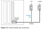
Example 3: New taps for both inverters and loads. This option is worth investigating where an existing feeder is available to serve both a new inverter system and a new load, but you would like to locate these at some distance away from the end of the feeder and avoid adding a panelboard. The strategy here is to make two Code-compliant taps, where one feeder tap conductor serves the inverter and the other feeder tap conductor serves the load. Figure 11 illustrates this two-tap scenario.
To ensure that the connections are Code compliant, size the inverter feeder tap conductor according to the larger value as determined by Equation 7a and 7b, and size the load feeder tap conductor according to Equation 6b.
240.21(5) Outside Taps of Unlimited Length.
Where the conductors are located outside of a building or structure, except
at the point of load termination, and comply with all of the
following conditions:
( 1) The tap conductors are protected from physical damage
in an approved manner.
(2) The tap conductors terminate at a single circuit breaker
or a single set of fuses that limits the load to the ampacity
of the tap conductors. This single overcurrent
device shall be permitted to supply any number of additional
overcurrent devices on its load side.
(3) The overcurrent device for the tap conductors
- Status
- Not open for further replies.