jumper
Senior Member
- Location
- 3 Hr 2 Min from Winged Horses
yeah but after the first few million I usually forget the question. and why I'm carrying this towel around.
Vogon: [being chased by Ford Prefect with a towel] He's got a TOWEL!
yeah but after the first few million I usually forget the question. and why I'm carrying this towel around.
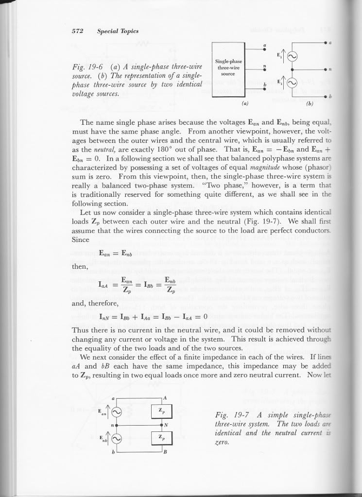
It was not like that in the original edition. Here is a page from my copy of the 1962 edition. I also find it interesting that Rick chose to crop off the remainder of the paragraph he quoted....I do have a little bit of of a concern with the use of + and - signs on an alternating current source.

Besoeker, I have been very patient with you for the past couple of days, but that patience has its limits when you keep flip-flopping in what you are saying. If you are unsure about your position, or are unable to communicate it using the English language, then you need to bow out of this discussion.I have not once suggested that there is a phase shift. As Mivey said, there is no shifting going on.
If you are suggesting that I lied, then state it! If you are suggesting that there was some information shown after my quote that I deliberately hid, then state it!I also find it interesting that Rick chose to crop off the remainder of the paragraph he quoted.
I suspect it is because he can't. I find it incredible that a EE would deny that the voltages are displaced by 180?. That fact is used in so many places in our field it just boggles the mind.I note also, that you have not come up with an alternative and credible explanation of why the neutral currents cancel that negates the obvious that they are displaced by 180deg.

I do not think you lied. It was not meant to be as dramatic as you are taking it.If you are suggesting that I lied, then state it!
I think you deliberately left off the rest of the paragraph.If you are suggesting that there was some information shown after my quote that I deliberately hid, then state it!
I'm not saying it was inappropriate as we are not talking about defending a murder rap.Don't pull this innuendo B.S. and suggest I did something inappropriate, but then fail to say what it was. If you can't substantiate your innuendo, then it just goes to show what dishonest lengths you will go to in an attempt to make a point. Can you substantiate your innuendo?
It would help if you would actually read his posts without trying to read into his posts.Besoeker, I have been very patient with you for the past couple of days, but that patience has its limits when you keep flip-flopping in what you are saying. If you are unsure about your position, or are unable to communicate it using the English language, then you need to bow out of this discussion.
Please post the quote as I must have missed that.You have emphatically stated that you must have a 180? phase shift
As far as I can tell, you are not reading what he is writing....but then deny making such a claim. You have affirmed that a phase shift is a time shift, but then later deny that. You've agreed with my previous assertions, but then later deny it.
Do you find that this communication method works for you in other areas? It is not a productive way to have a discussion. I have been around the block a few times and can tell you that most professionals I have met have very little respect for people who communicate that way. Whatever floats your boat I guess.I cannot carry on a discussion with someone that doesn't even know what their own position is about. If you don't understand what your position is, or can't decide what position you want to take, then leave the discussion to those that do understand.
I'm on the edge of my seat.Yes, I do have an answer for how neutral currents cancel, but we can't even get there until you figure out what your position is. It's a moving target, but if you sit still, I will hit it.
It wasn't included because it neither applied to nor refuted what I stated. You quoted the remainder of the text, so there is no secret about its contents. I gave a full bibliographical reference specifically so someone like you could not claim I misquoted.I think you deliberately left off the rest of the paragraph.
I'm not saying it was inappropriate as we are not talking about defending a murder rap.
I just think leaving off the other part was self-serving. Can't say I really blame you as you are under no obligation to present information that does not help your position. Interesting nonetheless.
Really? It was only 4 hours ago, and has been repeated quite often before that. Here is your quote.Please post the quote as I must have missed that.
That can only happen because of the 180deg displacement between the two wrt neutral.
Please underline/highlight the words "phase shift" in that quote.Really? It was only 4 hours ago, and has been repeated quite often before that. Here is your quote.
This comment did not slip past my purview. This may result in a warning from our moderator (and I apologize in advance), but I find it quite interesting that the only major participants battling against this discussion are those that have been in the business for 40, 50, 60 years, and their ways are so set that they cannot fathom allowing someone else to view a system different from themselves.It was not like that in the original edition. Here is a page from my copy of the 1962 edition.
Bes commented about the use of + and - symbols on the diagram. That was not they way the author originally drew it so he either changed his preference over the years or it was changed by the editor or publisher.This comment did not slip past my purview. This may result in a warning from our moderator (and I apologize in advance), but I find it quite interesting that the only major participants battling against this discussion are those that have been in the business for 40, 50, 60 years, and their ways are so set that they cannot fathom allowing someone else to view a system different from themselves.
Are you really arguing because this information is wrong, or because you have to have everyone do things your way?
"Center-Tapped Transformer and 120-/240-V Secondary Models" William H. Kersting:
Distribution engineers have treated the standard ?single-phase? distribution transformer connection as single phase because, from the primary side of the transformer, these connections are single phase and, in the case of standard rural distribution, single phase line to ground. However, with the advent of detailed circuit modeling, we are beginning to see distribution modeling and analysis being accomplished past the transformer to the secondary, which now brings into focus the reality that standard 120-/240-V secondary systems are not single-phase line-to-ground systems, but they are three-wire systems with two phases and one ground wire. Furthermore, the standard 120-/240-V secondary system is different from the two-phase primary system in that the secondary phases are separated by 180? instead of three phases separated by 120?.
"Handbook for Electrical Engineers" 1917, Harold Pender:
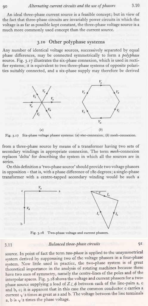
Strictly, the so-called single-phase system is a star-connected two-phase system, since the currents from the two terminals are in opposite directions at any instant, the current leaving by one and entering by the other. However, in practice the name two-phase system is used for a system supplied from a generator or other source of e.m.f. having two windings in which are developed two e.m.f.'s differing in phase by 90?; i.e., a two-phase system is in reality two distinct single-phase systems each with two terminals.
"M-I-C-K-E-Wye" Richard P. Bingham, Dranetz-BMI:
A "delta" circuit looks like the delta symbol, which is an equal-sided triangle. There are numerous variations of the delta circuit, such as: grounded deltas (one corner of the triangle is connected to a grounded conductor); open-leg delta (only two elements instead of three are used); or, crazy-leg (where one leg is center-tapped to produce two voltages that 180 degrees out of phase from each other).
"Navy Electricity and Electronics Training Series-Module 8?Introduction to Amplifiers-NAVEDTRA 14180 pg 1-7":
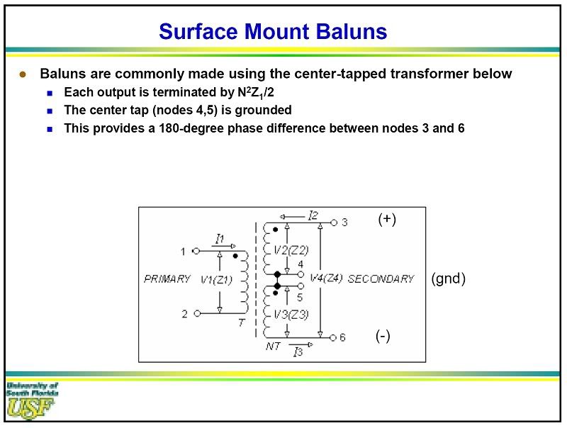
One way in which a phase splitter can be made is to use a center-tapped transformer. As you may remember from your study of transformers, when the transformer secondary winding is center-tapped, two equal amplitude signals are produced. These signals will be 180? out of phase with each other. So a transformer with a center-tapped secondary fulfills the definition of a phase splitter.
"Photovoltaic Power Systems and The National Electrical Code", Sandia National Laboratories:
In a utility connected system or with a 120/240-volt stacked pair of inverters, where the 120 /240-volt power consists of two 120-volt lines that are 180 degrees out of phase, the currents in the common neutral in the multiwire branch circuit are limited to the difference currents from any unbalanced load. If the loads on each of the separate branch circuits were equal, then the currents in the common neutral would be zero.

And your confusion is exactly why I am willing to risk my personal reputation on this topic to resolve this in light of some very adverse opposition.What I am having a hard time understanding.....
Who has refused to accept that? I have said more than once that both configurations are valid.What I am having a hard time understanding is those who refuse to accept that a center tapped transformer can have these secondary windings paralleled to only provide 120 volts, now if these two sections of windings were 180? out of phase I do not think this would work.
We can take an EMF to be in either direction. It is "jumping" at regular intervals and there is nothing that says jumping in one direction is anymore correct than jumping in the other. The source configuration does not completely define how we have to take the voltages from it. Please refer to some of the other information I have posted.Second in both posted books they both say that these two windings "being equal must have the same phase angle" but does say that "from another "view point" the voltages from the center (neutral) and the outer wires are 180? out of phase, so if this is a view point then it is using a instrument to view this wave being that would be an oscilloscope would make sense since the common input could only be connected to the center wire and then each red lead would connect to each end wire, this connection will have one red at A common at N and the other trace input red at B with will put B trace 180? out from A we should know that we have A+ A-N for the first 1/2 of the winding then B+N then B- for the second winding so if we look at our trace leads on B they are in reverse polarity with B's winding, this is where we are getting the 180? out of phase from????
does a winding jump 180? out of phase when you put a center tap on it?
Please refer to the other information I have posted and you will see that the voltages are real forces that can produce real work and are not just viewpoints.only if you reference the center tap with both black leads to the scope, this is the same with two batteries, +-+- the connection between the two batteries is common but not the same polarity with the other two ends and to properly read each battery you will have to place the red lead where there is a + sign and the black lead where there is the - sign this will cause a red and black lead on the common.
In both of the above the only thing out of phase is the "view point" not the windings or the batteries.
No one has suggested hooking up the voltages such that they are in opposition. They are hooked up in a manner such that they work in concert. Follow my post #98 and that should become clear to you.Oh by the way a DC Edison circuit with two batteries and a common connection will also have no common current when two identical loads are placed from this common to each end
And your confusion is exactly why I am willing to risk my personal reputation on this topic to resolve this in light of some very adverse opposition.
I am not the only person from this forum that opposes the misinformation that is being presented in this discussion, but I am apparently the only one willing to risk my reputation to stand up to it. I have taken a lot of hits for it, but it should be becoming clearer and clearer that these hits are less and less reputable.
I have been called a fool for going toe-to-toe with the "old boy's club", but if you pay attention to the discussion, you will note the complete absence of any information proving me wrong. To the contrary, what I state is supported by engineering text, yet the old-boys wish to dismiss this as tricks from the editor.
I am not foolish enough to think that I can teach the "ol' boys" that they are wrong, but I can at least make sure that other people are well informed as they make their own decisions.

