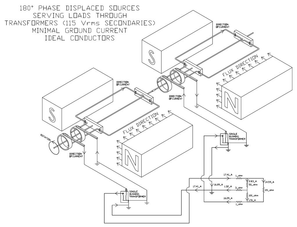
240v debate....

Status
Not open for further replies.
There is a significant difference between changing how one measures a voltage and physically changing what is being measured. When this topic last came up about 3 1/3 years ago, I put together this picture of batteries to help explain the concept. It is very similar to this discussion pertaining to a center tap transformer.

The right hand stack of batteries represents what happens when you "define" the system based on reversing your test leads. The image to the left is what happens when you simply relabel the system with a chosen reference point in the middle.

View attachment 5904

I'll bet you like me have a bunch of stuff like this all piled on to you hard drive from years ago LOL, between this computer my laptop and my old computer I don't know how many diagrams and charts and , and ,and, well just about everything you can think of. hurk27<<<< Master pack rat:lol:

When I got this computer I made sure I was going to have enough hard drive space for it all, so I ordered it with 2 500gig SATA rad 0 which shows up as over one T bite :roll:

Now all I got to do is get my old computer out of the basment and transfer all its stuff to this one, just haven't found that round tuit:happyno:
 
No, I'm even worse than you. I just searched, and I located a CADD drawing from October of 1993. Back then, the hard drive was only 20 meg. Right now I have 3 drives @ 2Tb, 1.5Tb, 500Gb. I never delete anything, and always keep a separate data drive from the operating system. The box is at least 10 or 12 years old, but everything was upgraded last winter when I put in a new motherboard. The 500Gb drive used to be the main drive and still contains the old operating system and programs that can't run on this motherboard.

I did another search and there are 26,510 jpg pictures. The key is a very rigid organization of everything. I even have email records dating back to 1995.
 
At 90? into the cycle, with L1 positive with N and L2 negative in respect to N then N has to comprise of being a negative and a positive just like in the series batteries, this is how they become an adder to get 240 volts. if you had two negatives at N you would not have 240 from L1-L2 no more then you would have 3 volts with two batteries in series with the negative ends together, so this using of the common point as a reference with both traces negative input leads on the common point is not referencing the two windings in their correct polarity.

If at 90? the correct polarity of each winding is A+---A-N|B+N----B- why would you try to reference the B+ with a black lead and place the red lead on the B- as we know this would reverse your reading the same as it would reverse a DC measurement this and only this is why you see a 180? displacement.

Also bringing in other types of circuits in to a discussion that was only about a transformer on a single phase 120-0-120 system made no sense other then to keep the discussion going.

Words spoken like a true electrician who has not boggled his mind with all that engineering bull crap that would complicate the art of boiling water.

AS my great granddaddy once said, ?show me an engineer with good common sense and I will show you a train.? Don?t know for sure just what he was talking about but sure enough Tweetise Railroad In Boone NC shore had an engineer for their train. http://tweetsie.com/
 
Words spoken like a true electrician who has not boggled his mind with all that engineering bull crap that would complicate the art of boiling water.

AS my great granddaddy once said, “show me an engineer with good common sense and I will show you a train.” Don’t know for sure just what he was talking about but sure enough Tweetise Railroad In Boone NC shore had an engineer for their train. http://tweetsie.com/

OK. Wow. Can't believe you guys. Good thread though. I've read every post since the beginning. And have followed this thread most days.

Several things come to mind:

At JWE: Thanks for noticing that Hurk can usually cut right through it. (As for boiling water: does steam rise from the water, or does the water condense when it hits the colder air above the water?)

Wow, 27 pages of postings in 12 days on such a simple issue. Post 264

At Jraef: 27 pages of postings will reduce to 15 pages of postings if you select for 20 posts on a page. (And, just for the record: 240 volts will reduce to 120 volts if you use half the coil, but the current will continue in the same direction/vector/whatever.)

Lol, no, but it really went somewhere I had not intended. :) post 271

At Stickboy1735 or whatever your number is (it might be 240 if you put your leads on the other way):

Glad you asked the question. Do you remember what it was? LOL.

How can two coils connected in series (or one coil that has a center tap) be 180 degrees in or out of anything? post 276

(it) is the common core flux that prevents it from happening with a center tapped coil. post 277

At JWE and Rick: Thanks. I assume the best JW, that your question was entirely rhetorical. And I also Rick, thanks for clarifying with the answer that JW was pointing at like a setter at the moment of flush.

Oh yeah, if I want to tell you have a nice day-I can.:p

At Jumper: thanks for being such a nice guy.

At all: Thanks all. I actually appreciate everyone who has posted questions, answers, or whatever.;) I'm starting to really like the forum.

As you might guess, I agree with the guys who don't want BS.

... that is a joke, or not.


:):D:thumbsup::thumbsup::thumbsup:
 
Wait, let me get this straight. You are arguing over a "descriptor"?
Not at all.

You think a "180? difference" is OK, but if you call it a "180? phase shift" it is somehow not the same thing?
It isn't the same thing. Nothing is getting shifted. I think that might be where you are misunderstanding it.
I can produce a phase shift with an RC network and even a variable phase shift with a bit of electronics. Actually, I posted the transformer section of a circuit I designed that does just that.
Have you done similar work?

It doesn't matter what you want to label it. When you stick the 180? into your voltage, the effect is the same. It is a "difference", "time shift", "phase shift", "phase relationship", "displacement", or what ever else you want to call it. It is the same thing. Do you honestly believe that giving it less offensive name makes it do something different with your voltage waveform?
It isn't the same thing at all. It is neither a phase shift nor a time shift.
My post #22 showed instantaneous values. No time shift whatsoever. No 8ms delay.

And I note that you have yet to answer the question I posed in post #109.
Or submitted your explanation of why the neutral currents cancel though in post #223 you stated that you do have an answer.
I urged you in post #270 to get on with it. You have not done so as far as I can tell.
But, to give you the benefit of the doubt, I accept that you might have done so and I might have missed it in all the detritus.
I'm inclined to think not but correct me if I'm mistaken about that.
 
It isn't the same thing at all. It is neither a phase shift nor a time shift.
Then what do you call it?


But the reality is, it only exists because the scope you chose to use can only display Van and Vbn instead of Van and Vnb.
Take two loads and connect them in series and to the 240V source - no other connection. Now use your scope to examine the drop voltage across each load, at the same time. Are the displayed voltages predictable using KVL and the single current in this 2-wire loop?
 
It isn't the same thing. Nothing is getting shifted. I think that might be where you are misunderstanding it.

<snip>

It isn't the same thing at all. It is neither a phase shift nor a time shift.
If it is neither a phase shift or time shift, what is it?

What do you think is happening with that 180-degrees that you want to interject into your voltage waveform? Does it just lay around getting a suntan? Does it turn your scope sideways? :happysad:

Here is another excerpt from Hayt and Kemmerly, pages 269-270.

PhaseAngle.jpg
 
explanation of why the neutral currents cancel though in post #223 you stated that you do have an answer.

I do.

Because when two nodes that are in-phase and each has a load applied share a common wire the current flow will be both directions in this common wire, and when this current is equal they will cancel each other, this is the only point where you will have two currents 180? out of phase, and it is not because the source is out of phase but because the flow of electrons coming from or going to each load in this conductor that is out of phase.

The same goes when conductors are run in the same conduit, the current flow to a load equals the current flow back to the source same thing as before but different conductors, you have current flowing in two different direction in this conduit and because they are equal they cancel, it is not the flow of the electrons as a whole in the circuit but the flow of the electrons in the circuit passing each other in this conduit.

Simple way to grasp this is to draw a circle with a supply at the top and a load at the bottom and put arrows around it in one direction, now bring the left and right side of this circle close together and draw a conduit around them and you will see even though you have not altered your arrows that one will be pointing up and one will be pointing down = 180? but the circuit is still in-phase
 
Last edited:
With every posting you make, it is becoming more and more obvious that the only basis for your arguments is that you are mandating everyone to conform to your ways. Not because they are wrong, but because you need everyone to do as you do.

You're losing ground Mivey.
Neurotic projection: perceiving others as operating in ways one unconsciously finds objectionable in oneself.
No, let's not ignore mesh analysis....let's embrace it!!

Here you go Mivey. Here is a 120/240V system with all of the mesh analysis descriptors already placed for you. I re-labeled the B-Phase source for 115@180. Just in case you thought I might be lying, I removed the inductor for simplicity, but left the symbol so you knew it was originally present. I wouldn't want you to think I was being secretly deceptive.

Please tell us how you are able to complete this analysis without having your B-Phase current not contradict your B-Phase voltage! (Watch your minus signs, because you darn well know I will be watching them.)
Before we let you take on the task of watching other's minus signs, how about we get you to the point where you can draw a circuit correctly?

Look at the following and see if you can figure out what was drawn incorrectly in your circuit:

180deg2-PhaseGenerator-withcircuit.jpg
 
This thread has taught me one thing if nothing else.

Stupidity is gained with education. The more we learn the more stupid we get.

The easy way to solve this question is to forget all about the phase angles and time wraps and go to a simple lab experiment that we all can do.

Take a two cell flash light and insert the power supply first in line and then 180 degrees out of line and record what happens.

Nothing wrong with wanting to keep things simple. Not everyone wants to learn more. You can be the champion for ignorance if you want, and others can follow their own star and learn more if they want, but learning more will not make them stupid.

Stupidity is a condition, not a function of how much you know. I know plenty of educated idiots. I know plenty of ignorant idiots as well. Education is not the problem.

I believe I asked this question a year or so ago. IIRC, his(?) answer was it didn't make a difference.
That is because the voltage will have a 180? angle, as will the current. Think about it. The voltage can be taken in either direction and in my open-wye example we do exactly that with the single-phase transformers, and yes we get real voltages even though we take the pressures in different directions in either half of the winding. This is basic electricity.

Have you considered how center-tap baluns are used to get 180? phase-displaced signals for a balanced signal?
 
As for calling the other EEs in this thread "old school", I find that funny-especially concerning Mivey (I cannot comment on Bes, David, or Lazlo-I do not know them well enough to comment without their permission, although I have great respect for all three, as I do I for you).

Mivey merely points out the different aspects involved in looking at a particular install. He never thinks inside the box, he makes people think outside it. Mivey-conventional-ya gotta be kidding. He is like no EE I have ever met.
Very kind of you to say so. If people would take the time to look beyond the traditions they have held for so long and try to understand where they came from, they will be better for it. Not everybody wants to do that and I have no problem with that. I know many fine people who are just not interested in thinking beyond what they are comfortable with, but they have other qualities that I admire.
 
Wait, let me get this straight. You are arguing over a "descriptor"? You think a "180? difference" is OK, but if you call it a "180? phase shift" it is somehow not the same thing? It's not about the words that follow the 180? that matter. It is the 180? that matters.

It doesn't matter what you want to label it. When you stick the 180? into your voltage, the effect is the same. It is a "difference", "time shift", "phase shift", "phase relationship", "displacement", or what ever else you want to call it. It is the same thing. Do you honestly believe that giving it less offensive name makes it do something different with your voltage waveform? Shouldn't we be having a Bill Clinton joke in here somewhere?
I have already tried to explain the issue is that you will not find consistency in terms in our industry. Some fields use phase shift to mean a shift in time such that the waveforms will have different creation points in time. It may also mean that two waveforms reach a positive peak at different times. It seemed you were trying to lead Bes into saying that there had been a shift in the creation point when there had not been.

We have been trying to distinguish between the 180? that does mean a shift in creation time and the 180? that means a physical shift in phase displacement. FWIW, some fields use the term "phase shift" to mean a change in the creation time and while others use it to mean a physical displacement.

From what I have observed, you have a tendency to take what someone says and try to twist it into something to argue against. If you would quit doing that, and opt instead to try to understand what someone is saying, the discussion would go a lot smoother.

I have a question and I am serious about the question is someone would please take some time and help me.

How can two coils connected in series (or one coil that has a center tap) be 180 degrees in or out of anything?
:?

Because, again, we can take the electromotive force to be in either direction because the choice is completely arbitrary.

Also bringing in other types of circuits in to a discussion that was only about a transformer on a single phase 120-0-120 system made no sense other then to keep the discussion going.

That was not the purpose. If you would go back, and are able to follow what I said, you would be able to see the point I was trying to make. I'll be glad to elaborate if you are really interested in understanding.
 
Words spoken like a true electrician who has not boggled his mind with all that engineering bull crap that would complicate the art of boiling water.
I am an electrician as well as an electrical engineer. I can respect the fact that you want to keep things simple as not everyone has the desire to expand their knowledge beyond their comfort zone. I will agree that it can be complicated for some and really will not impact the life of the day-to-day EC as it is not going to change what we do. This is a brain excercise and as a member like everyone else, you are free to participate or not.
 
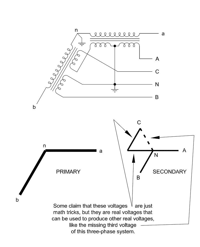
Stay away from a wye connection. We have been focusing on the 2 voltages 'found' in a 120/240V system derived from a center tapped transformer.
The point is that we use the two voltages in the center-tap single-phase transformer in two different directions, not just once but in both center-tap single-phase transformers. You have claimed that taking the voltage in two different directions from the two halves is just a math trick and is not a physical reality. The way I used the windings in the open wye example is in direct conflict with what you have claimed and produces real voltages.
 
The point is that we use the two voltages in the center-tap single-phase transformer in two different directions, not just once but in both center-tap single-phase transformers. You have claimed that taking the voltage in two different directions from the two halves is just a math trick and is not a physical reality. The way I used the windings in the open wye example is in direct conflict with what you have claimed and produces real voltages.

Here is a different diagram that may make it clearer:

Open-Wyeto4WWye.jpg


This should make it clear that even though the primary of each of the single-phase transformers is a single phase voltage, we can take the secondary voltages of the winding halves in either direction or even in different directions.

As I have said before, the way the voltages are created and the way we take them from that source can be different.
 
Someday you will provide results of a simple loop analysis using the 120/240V center tapped transformer we have been discussing, without straying into the world of three-phase systems.

Take two unequal size resistors, connect them in series, power them from a 240V 2-Wire source.
Does the loop current have the same phase angle as the voltages across each resistor?
Do the voltages across the resistors have the same phase angle as the source voltage?
Is the loop current in phase with the source voltage?

Take the exact same resistors in series, except power them from a 240V 2-Wire source created from (2) 120V supplies connected in series.
Does the loop current have the same phase angle as the voltages across each resistor?
Do the voltages across the resistors have the same phase angle as the (2) supply voltages?
Is the loop current in phase with each of the supply voltages?
 
Someday you will provide results of a simple loop analysis...power them from a 240V 2-Wire source...Take the exact same resistors in series, except power them from a 240V 2-Wire source created from...
FYI, we have not been discussing a two-wire source. If we have two wire sources it is one thing, but when you have a neutral, you have a three-wire source.
 
...without straying into the world of three-phase systems....
It is a shame you do not take the time to see that the example was about the single-phase transformers.

The three-phase system's use of the single-phase transformers is just an example that is ideal because it makes use of the bi-directional option of the single-phase center-tap transformers to produce voltages that everybody can see and agree with because they are voltages that fall in the traditional "comfort zone".
 
Status
Not open for further replies.
Top