250.30(A)(3) Exception No. 2 & it?s use

Status
Not open for further replies.

dnem

Senior Member
Location
Ohio
So the GEC will terminate at the source bus and not the CEE, how would you interpret this?

source bus, concrete encased electrode, building steel, watermain, groundrod, which electrode you pick doesn't matter. . The only consideration is if your source termination point is part of the Grounding Electrode System.

Has the concrete encased electrode been already bonded to the source bus ? . If yes, then take your pick, 250.30(A)(7)Ex1 uses the word "available" which "throws the barn door open" for you to pick whatever electrode you wish.

Remember in '02 when 250.50 used the word "available". . Footer rebar electrode bonding was completely voluntary. . Then '05 changed the word to "present" and it completely changed CEE enforcement.

250.30(A)(7)Ex1 says "available", so pick a spot on the electrode system that's available to you.
 

dnem

Senior Member
Location
Ohio
PS
don't get confused by the wording in 250.30(A)(3), "This connection shall be made at the same point on the separately derived system where the system bonding jumper is connected." . That is talking about the load end of the Electrode GEC. . The line/supply end can go anywhere on the Grounding Electrode System.
 

tryinghard

Senior Member
Location
California
PS
don't get confused by the wording in 250.30(A)(3), "This connection shall be made at the same point on the separately derived system where the system bonding jumper is connected." . That is talking about the load end of the Electrode GEC. . The line/supply end can go anywhere on the Grounding Electrode System.

I understand this. I did not realize the source panel bus is considered part of the grounding system I thought this end had to terminate to "an electrode" to be considered a GEC.
 

tryinghard

Senior Member
Location
California
Interesting, 250.30(A)(5) "Installation" of GEC specifies it ?shall comply with? 250.64(A), (B), (C), & (E).

The GEC is the conductor between the grounding electrode and the destination bus (or visa versa), this conductor is to be continuous but at least installed as per 250.64(C).

250.30(A)(7)Ex1 says "available", but it is talking about the use of an electrode not the termination to one. ?Any of the other electrodes indentified in 250.52(A) shall be used where the electrodes specified by 250.30(A)(7) are not available.?

I do not see where the NEC says the GEC can terminate on the grounding system.

Where does NEC accept a panel bus as acceptable termination point to the grounding electrode?
 

dnem

Senior Member
Location
Ohio
I do not see where the NEC says the GEC can terminate on the grounding system.

Where does NEC accept a panel bus as acceptable termination point to the grounding electrode?

250.24(A)(1), "The grounding electrode conductor connection shall be made at any accessible point ..... including the terminal or bus to which the grounded service conductor is connected at the service disconnecting means."

250.24(A)(4), "..... the grounding electrode conductor shall be permitted to be connected to the equipment grounding terminal, bar, or bus to which the main bonding jumper is connected."

Forget about the SDS transformer for a minute.

If you have a building with metal water pipe, 250.52(A)(1) + a #3/0 GEC, metal frame, 250.52(A)(2) + a #3/0 GEC, footer rebar, 250.52(A)(3) + a #4 GEC, ground ring, 250.52(A)(4) + a #3/0 GEC, ground rod, 250.52(A)(5) + a #6 GEC. . You have 5 GECs terminating at the main disconnect. . You have three #3/0, a #4, + a #6. . Are you going to make one huge cad weld around the grounded conductor lug ? . Aren't you going to terminate on multiple lugs all bolted to a bar or bus ?

We're not talking about a phase bus here. . This is the main disconnect grounded/grounding "triple duty" bus with lugs for the service neutral, all feeder neutrals [Grounded], all feeder equipment grounds [EGCs], and all electrode grounds [GECs].

"I do not see where the NEC says the GEC can terminate on the grounding system"
Why are you designating that bus as the grounding system bus ?

The grounded/grounding bus of the main disconnect is the connection point of all 3 independent grounded/grounding systems. . The grounded conductors are bonded there, the equipment grounding conductors are bonded there, and the grounding electrode conductors are bonded there.

And if it's 2 or three independent buses connected by wire or busbar, nothing changes [250.24(A)(4)+250.64(C)(2)].
 

tryinghard

Senior Member
Location
California
250.24(A)(1), "The grounding electrode conductor connection shall be made at any accessible point ..... including the terminal or bus to which the grounded service conductor is connected at the service disconnecting means."

250.24(A)(4), "..... the grounding electrode conductor shall be permitted to be connected to the equipment grounding terminal, bar, or bus to which the main bonding jumper is connected."

This is the main disconnect grounded/grounding "triple duty" bus with lugs for the service neutral, all feeder neutrals [Grounded], all feeder equipment grounds [EGCs], and all electrode grounds [GECs].

David, I really appreciate your effort explaining to me. But my case is expanding another GEC downstream past the bus to a SDS, all your examples above specify the ending termination of the GEC from the grounding electrode.

Check out the graphic below as example, we?re talking about expanding another GEC from the Service Disconnects bus to a transformer downstream. This bus essentially is replacing the termination of an electrode, in other words the new GEC will terminate at the transformer routing from a distribution bus rather than an electrode, there?s no physical electrode involved.

250.30(A)(3) & (5) do not seem to support this, in fact (A)(3) says the GEC ?shall be used to connect the grounded conductor of the derived system to the grounding electrode?. So where does the NEC allow the GEC to continue past the destination bus termination?

1113854601_2.jpg
 

tryinghard

Senior Member
Location
California
Here is another visual of what your suggesting:

XFMRElectrode.jpg
The NEC address’ supplemental electrodes conductor termination 250.53(D)(2) to be installed like your suggesting except one electrode would be the transformer.

1113918661_6.jpg


Actually the new GEC is connecting to another GEC rather than an electrode. This is why I am curious about adding another ground electrode, then just bonding it to the other as per 250.53; similar to a supplemental.
 
Last edited:

dnem

Senior Member
Location
Ohio
I was following you right up until your last question

So where does the NEC allow the GEC to continue past the destination bus termination?

destination is load side and is on the SDS transformer end
supply is line side and is on the service end

Up until that question you referred to the "Service Disconnects bus" [supply/line side service end]. . You referred to the "distribution bus". . Do you mean in the service ? [supply/line side service end], or in the SDS first disconnect ? [destination/load side SDS end]

Can you rephrase your question ?
 

dnem

Senior Member
Location
Ohio
Here is another visual of what your suggesting:

XFMRElectrode.jpg

Yes, I agree

250.30(A)(3) & (5) do not seem to support this, in fact (A)(3) says the GEC ?shall be used to connect the grounded conductor of the derived system to the grounding electrode?. So where does the NEC allow the GEC to continue past the destination bus termination?

It's not 250.30(A)(3) that concerns me. . Yes, it says connect to an electrode but (5) tells you how to connect and (5) is troubling me. . I notice that 250.30(A)(5) sends you to 250.64 but only specifies (A), (B), (C), + (E). . There is a very conspicuous abscence of (F) and that troubles me because it's (F)(3) that allows you to terminate on a busbar.

So here's the solution:

You were planning on pulling the electrode GEC inside the feeder conduit from the service main to your SDS, right ? . So, for the transformer SDS electrode GEC termination on the supply/line end at the service, when you enter the service enclosure from the feeder conduit, rather than bolt the SDS electrode GEC to the service grounded/grounding bus, instead compression crimp it to one of the existing electrode GECs that is running between an existing electrode and the service grounded/grounding bus. . This compression crimp is allowed in the SDS section of Article 250 at 250.30(A)(5) which refers you to 250.64(C) which contains 250.64(C)(1) and makes your electrode GEC continuous all the way the an actual electrode itself.
 

dnem

Senior Member
Location
Ohio
Here's another possible solution [but only if you know what's in the floor under the new SDS]:

Drill a hole in the concrete next to your SDS transformer or next to its first secondary disconnect. . Pound a ground rod thru the hole. . Decide if you are going to put your system bonding jumper in the new SDS transformer or in the first disconnect on the secondary of the SDS transformer [250.30(A)(1)], "any single point". . Next run an electrode wire GEC from that "single point" that you chose to the new ground rod [250.30(A)(3)]. . Don't worry that 250.30(A)(7) says (1)"waterpipe" or (2)"structural steel" because Ex1 says "available" so you are going to chose the "available" ground rod. . Next run an electrode wire bonding jumper [250.53(C)] from the new ground rod, thru the feeder conduit and all the way back to your service disconnect location. . Final bolt the jumper onto the grounded/grounding bus [250.64(F)(3)].
 

dnem

Senior Member
Location
Ohio
I need to ask a question

Very early in this thread confusion arose about intermixing equipment EGCs + electrode GECs and I think that has been covered thoroughly [But if I'm wrong about the assumption, we can continue that discussion].

But also early in this thread [post #3], the thought of using 250.30(A)(3)Ex2 was eliminated, and that option was dropped without much conversation.

post #3
250.30 (A) (3) exception 2 says where a separately derived system originates in listed equipment suitable as service equipment, that exception does not apply to your installation

post #5
In what way though, the primary circuit does originate in suitable equipment the transformer just doesn?t reside there?

post #8
they are talking about service equipment switchgear that has a transformer section

I see that 250.30(A)(3)Ex2 say, "listed equipment suitable as service equipment". . It doesn't say used as service equipment. . A similar example is a one building feeding another. . In 225.36 the second building needs a disconnect "suitable for use as service equipment" but the second building doesn't contain the service itself. . It's feed with a feeder.

MPD,
What information or reasoning can you provide that would show that 250.30(A)(3)Ex2 is restricted to service equipment switchgear that has a transformer section ?
 

tryinghard

Senior Member
Location
California
Here's another possible solution [but only if you know what's in the floor under the new SDS]:

Drill a hole in the concrete next to your SDS transformer or next to its first secondary disconnect. . Pound a ground rod thru the hole. . Decide if you are going to put your system bonding jumper in the new SDS transformer or in the first disconnect on the secondary of the SDS transformer [250.30(A)(1)], "any single point". . Next run an electrode wire GEC from that "single point" that you chose to the new ground rod [250.30(A)(3)]. . Don't worry that 250.30(A)(7) says (1)"waterpipe" or (2)"structural steel" because Ex1 says "available" so you are going to chose the "available" ground rod. . Next run an electrode wire bonding jumper [250.53(C)] from the new ground rod, thru the feeder conduit and all the way back to your service disconnect location. . Final bolt the jumper onto the grounded/grounding bus [250.64(F)(3)].

This was what I tried to convey in Post 9, and it appears I can terminate the electrode bonding jumper through the distribution along the way to the service disconnect.

So I'd really be installing a grounding electrode jumper between the electrodes. :)
 

tryinghard

Senior Member
Location
California
I need to ask a question

Very early in this thread confusion arose about intermixing equipment EGCs + electrode GECs and I think that has been covered thoroughly [But if I'm wrong about the assumption, we can continue that discussion].

Nope I understand the GEC cannot be used as an EGC and visa versa.

But also early in this thread [post #3], the thought of using 250.30(A)(3)Ex2 was eliminated, and that option was dropped without much conversation.

I see that 250.30(A)(3)Ex2 say, "listed equipment suitable as service equipment". . It doesn't say used as service equipment. . A similar example is a one building feeding another. . In 225.36 the second building needs a disconnect "suitable for use as service equipment" but the second building doesn't contain the service itself. . It's feed with a feeder.

This is the place of my original thoughts as well, and I am still curious :-?

MPD,
What information or reasoning can you provide that would show that 250.30(A)(3)Ex2 is restricted to service equipment switchgear that has a transformer section ?
 

tryinghard

Senior Member
Location
California
Seem?s to me the only real compliant grounding at this place is another electrode and bonding jumper. Unless 250.30(A)(3)Ex2 is deemed compliant.

XFMRElectrodeb.jpg
 

dnem

Senior Member
Location
Ohio
Seem?s to me the only real compliant grounding at this place is another electrode and bonding jumper. Unless 250.30(A)(3)Ex2 is deemed compliant.

I told you another option which doesn't require adding a ground rod and I gave you the code sections to back each part of the option.

You were planning on pulling the electrode GEC inside the feeder conduit from the service main to your SDS, right ? . So, for the transformer SDS electrode GEC termination on the supply/line end at the service, when you enter the service enclosure from the feeder conduit, rather than bolt the SDS electrode GEC to the service grounded/grounding bus, instead compression crimp it to one of the existing electrode GECs that is running between an existing electrode and the service grounded/grounding bus. . This compression crimp is allowed in the SDS section of Article 250 at 250.30(A)(5) which refers you to 250.64(C) which contains 250.64(C)(1) and makes your electrode GEC continuous all the way the an actual electrode itself.
 

tryinghard

Senior Member
Location
California
I told you another option which doesn't require adding a ground rod and I gave you the code sections to back each part of the option.

You were planning on pulling the electrode GEC inside the feeder conduit from the service main to your SDS, right ? . So, for the transformer SDS electrode GEC termination on the supply/line end at the service, when you enter the service enclosure from the feeder conduit, rather than bolt the SDS electrode GEC to the service grounded/grounding bus, instead compression crimp it to one of the existing electrode GECs that is running between an existing electrode and the service grounded/grounding bus. . This compression crimp is allowed in the SDS section of Article 250 at 250.30(A)(5) which refers you to 250.64(C) which contains 250.64(C)(1) and makes your electrode GEC continuous all the way the an actual electrode itself.

I think I may install the electrode and bonding jumper because this crimp is not so user friendly inside the panel enclosure (space).
 

tryinghard

Senior Member
Location
California
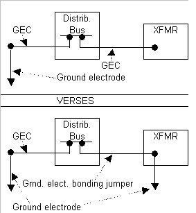
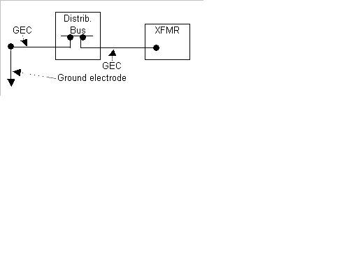
No matter how this transformer gets grounded there are at least 3 distinctive items involved:

  • [1] ? Grounding electrode
    [2] ? Grounding electrode conductor
    [3] ? Grounding electrode bonding jumper

I would vote for the lesser of 3 weird ways (and it really seem?s compliant) and that?s weird way #1, its weird because the bonding jumper will terminate in a panelboard before is gets to the service disconnects bus.

Weird way #1 -- Install a driven grounding electrode near the transformer:

250.30(7) -- ?Grounding electrode shall be as near as practicable to and preferably in the same area as the GEC connection to the system.?

250.30(5) -- ?Grounding electrode conductor shall comply with 250.64 (A), (B), (C), & (E)?

250.50 -- ?All Grounding electrodes?shall be bonded together to form a grounding electrode system.?

250.53 ? ?The bonding jumper(s) used to connect the grounding electrodes together to form the grounding electrode system shall be installed in accordance with 250.64 (A), (B), & (E)?, seems to collide with 250.30(5).

250.64 (A), (B), & (E) ? will qualify the required grounding electrode bonding jumper(s) installation.

Weird way #2 ? Use existing grounding electrode system that includes only a CEE?s grounding electrode conductor at the service disconnect ground bus (main distribution board)

250.30(A)(3) ? ?A grounding electrode conductor?shall be used to connect the grounded conductor?to the grounding electrode.?

250.30(A)(5) -- ?Grounding electrode conductor shall comply with 250.64 (A), (B), (C), & (E)?

250.64 (C ) ? ?Grounding electrode conductor shall be installed in one continuous length without splice or joint except as permitted in (1) through (4).? This application would require a splice.

312.8 ? Qualifies the area needed to splice in a panel, this is an old enclosure space was not common so this is not likely.

Weird way #3 ? Use the feeder equipment ground for the GEC

250.30(A)(3) Ex 2, may really not be compliant?

What a trail! Any other thoughts, direction, reprimand...
 

tryinghard

Senior Member
Location
California
Here?s a thought/possibility prodded from Goroon, at Post 3 (of ?Column base grounding?), it is in regards to bonding electrodes and 2008 NEC.

250.52 Grounding Electrodes.
(A) Electrodes Permitted for Grounding.

(3) Concrete-Encased Electrode...?Where multiple concrete-encased electrodes are present at a building or structure, it shall be permissible to bond only one into the grounding electrode system.?

This does say multiple CEE?s specifically, but can we rely on the equipment ground to bond additional ground electrodes?
 

dnem

Senior Member
Location
Ohio
This does say multiple CEE?s specifically, but can we rely on the equipment ground to bond additional ground electrodes?

No, it means that only one concrete encased electrode [defined as: min 20' of 1/2" rebar or 20' of bare #4 encased plus a tail sticking out] is required to be bonded as an electrode to the service. . You can ignore [not bond] the others that might exist in the pour that are seperate. . So if you have multiple independent 20' CEE sections in each building, you are allowed to ignore all except one per building.

"equipment ground to bond additional"
No, don't bond them at all or bond them with an electrode GEC according to GEC requirements/rules.
 
Status
Not open for further replies.
Top