Ya, so what. Both answers are correct and no one is disputing that--except maybe you. If you think that our two answers are different, then you need to bone-up on your vector analysis. The only difference between our two drawings is that mine is prettier than his.
")
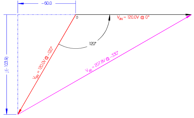
If I was not too lazy to place the labels "A" and "B" on the diagram, that is all it takes to properly identify the phase angle. This is the same mistake you made that started this whole discussion two weeks ago. You are assigning arrow heads according to your interpretation of the circuit, and that is not how phasor diagrams work.
I have repeated this so many times that I am growing tired of saying the same thing without you acknowledging it. I have not contested how you choose to identify your voltages in your circuit diagrams, but when you create a phasor diagram, it is a solution to the problem, and the phasor directions are independent of the original assumptions.
A phasor diagram is a graphical solution to a mathematical problem. As I said before, when solving a scientific or mathematical problem, it doesn't matter where someone starts or how they get to the final answer, ALL final answers must be the same. If your answer differs from the norm, then it means you have made a mistake in your methodology.