ELA
Senior Member
- Occupation
- Electrical Test Engineer
This post was made to add to a discussion that has come up from time to time as to what an AFCI breaker does when its test switch is pushed. Many here are familiar with what the GFCI test switch does but I have not seen anything on the test function of the AFCI.
I have read several articles on the AFCI but have been unable to get great detail or much of anything about how the test switch worked.
In an attempt to gain some understanding I disassembled a QO115AFCI and began examining the circuits inside and performing tests. My intent is to share experimentally derived information about the inner workings of the one particular AFCI that I examined. I do not claim to be an expert on AFCIs nor do I hold that all of my work is flawless or 100% accurate.
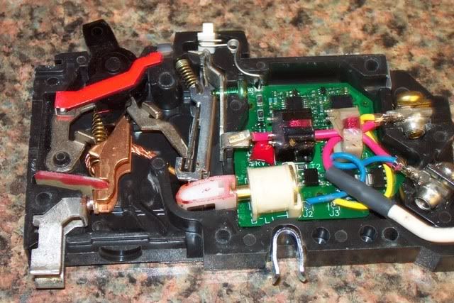
Here is a photo of the AFCIs insides:

Click for large version
The black coil on the center right may be referred to as the “Injection/arc sense” coil. The white coil to the right will be referred to as the “leakage sense” coil.
As seen in the picture only the red wire “hot” is inside of the black core. Both the hot and the neutral wires are inside of the leakage detect core.
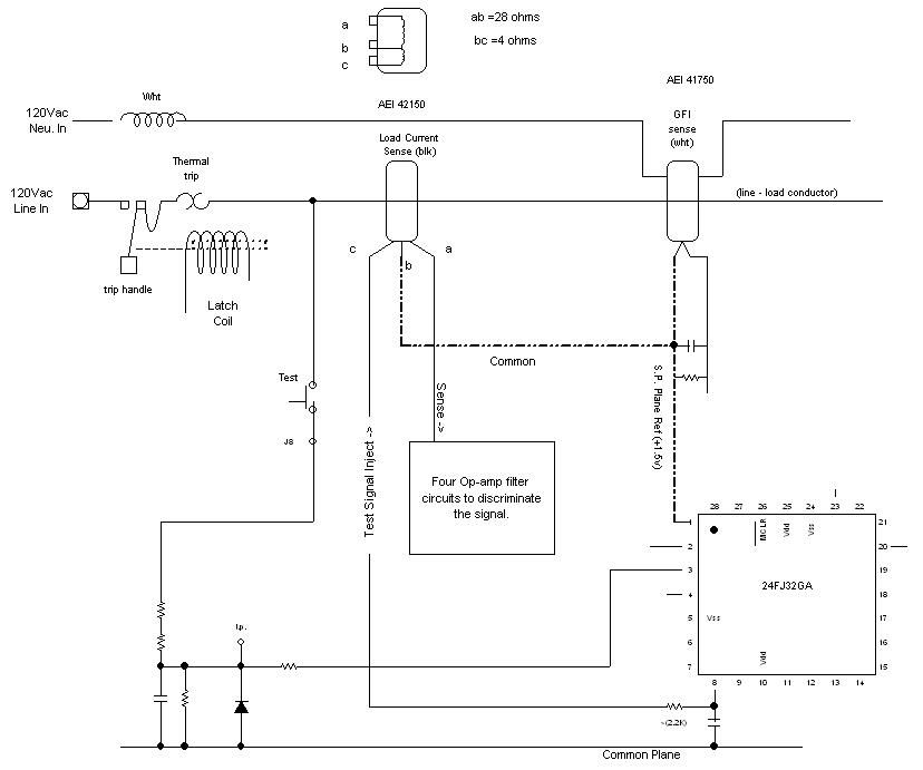
The black coil has two windings measured at roughly a 7:1 (dc resistance) ratio. A partial schematic below shows that one winding (bc) is used to inject a signal for test purposes. This coil connects to pin 8, an output, of the microcontroller. The other coil (ab), with a higher winding count senses current in the hot conductor , or currents injected by the injection coil.

The test button is simply an input to the microcontroller. When the test button is pushed the microcontroller does not produce a “true arc fault condition”. Instead it “injects signals” into the (bc) winding of the black coil. The signals injected there are then coupled into the (ab) winding. Several op-amp filters are connected to the (ab) winding that then feed multiple inputs to the microcontroller for analysis.
Since it would be prohibitive for this device to produce an actual high current arc it instead tests its ability to sense certain frequencies that are used in the analysis of an arc signature. Since this black core is crucial to the ability to sense an arc fault the integrity of it is what is tested. It was found that when the black coil was physically removed from the circuit board that the circuit breaker test button would no longer work (indicating a problem). However I could remove the red wire from the middle of the core and the breaker would still test ok!
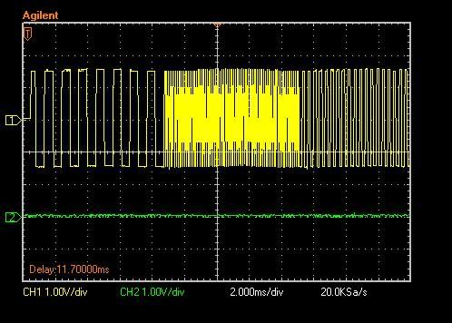
The output of the microcontroller that feeds the (bc) coil was then monitored while the test button is pressed and the results are shown below:

When the test button of the AFCI is pressed the microcontroller outputs this waveform from pin 8 that lasts approximately 25 milliseconds.
From this it can be seen that the microcontroller puts out three distinct frequencies. First it outputs a signal at approx. (1Khz) , it then changes to a higher frequency of approx. (10Khz) , and finally back down to (2.5Khz).
Each frequency band lasts for 1/3 of the total or equal to a one-half cycle duration at 60hz.
This sequence lasts for 25 milliseconds and the breaker then trips. Note this is less than the 5 half- cycles I have read were required as a minimum to sense a true arc.
Based on this limited data, on this one product example, it appears that the test button confirms the integrity of its internal circuitry by simulating the high frequency aspects of a true arc.
It then couples these high frequencies into its sense circuitry to assure that those circuits are capable of registering the high frequency content of an arc.
I performed a lot more testing after this to the point where I was able to simulate an arc and trip the breaker. I could share more if there is any interest.
I am afraid I may have already put too much into one posting and bored you all :smile:
I have read several articles on the AFCI but have been unable to get great detail or much of anything about how the test switch worked.
In an attempt to gain some understanding I disassembled a QO115AFCI and began examining the circuits inside and performing tests. My intent is to share experimentally derived information about the inner workings of the one particular AFCI that I examined. I do not claim to be an expert on AFCIs nor do I hold that all of my work is flawless or 100% accurate.
Here is a photo of the AFCIs insides:

Click for large version
The black coil on the center right may be referred to as the “Injection/arc sense” coil. The white coil to the right will be referred to as the “leakage sense” coil.
As seen in the picture only the red wire “hot” is inside of the black core. Both the hot and the neutral wires are inside of the leakage detect core.
The black coil has two windings measured at roughly a 7:1 (dc resistance) ratio. A partial schematic below shows that one winding (bc) is used to inject a signal for test purposes. This coil connects to pin 8, an output, of the microcontroller. The other coil (ab), with a higher winding count senses current in the hot conductor , or currents injected by the injection coil.

The test button is simply an input to the microcontroller. When the test button is pushed the microcontroller does not produce a “true arc fault condition”. Instead it “injects signals” into the (bc) winding of the black coil. The signals injected there are then coupled into the (ab) winding. Several op-amp filters are connected to the (ab) winding that then feed multiple inputs to the microcontroller for analysis.
Since it would be prohibitive for this device to produce an actual high current arc it instead tests its ability to sense certain frequencies that are used in the analysis of an arc signature. Since this black core is crucial to the ability to sense an arc fault the integrity of it is what is tested. It was found that when the black coil was physically removed from the circuit board that the circuit breaker test button would no longer work (indicating a problem). However I could remove the red wire from the middle of the core and the breaker would still test ok!
The output of the microcontroller that feeds the (bc) coil was then monitored while the test button is pressed and the results are shown below:

When the test button of the AFCI is pressed the microcontroller outputs this waveform from pin 8 that lasts approximately 25 milliseconds.
From this it can be seen that the microcontroller puts out three distinct frequencies. First it outputs a signal at approx. (1Khz) , it then changes to a higher frequency of approx. (10Khz) , and finally back down to (2.5Khz).
Each frequency band lasts for 1/3 of the total or equal to a one-half cycle duration at 60hz.
This sequence lasts for 25 milliseconds and the breaker then trips. Note this is less than the 5 half- cycles I have read were required as a minimum to sense a true arc.
Based on this limited data, on this one product example, it appears that the test button confirms the integrity of its internal circuitry by simulating the high frequency aspects of a true arc.
It then couples these high frequencies into its sense circuitry to assure that those circuits are capable of registering the high frequency content of an arc.
I performed a lot more testing after this to the point where I was able to simulate an arc and trip the breaker. I could share more if there is any interest.
I am afraid I may have already put too much into one posting and bored you all :smile:
Last edited by a moderator:

