Battle of the Phases

Status
Not open for further replies.

rattus

Senior Member
quogueelectric said:
The single phase xformer is not really 180 dg out of phase. We will freeze time to demonstrate what is happening by going to 2 batteries in series. One baterry is 1.5 volts from - to+ +being you 120 and negative being your grounded leg When you have 2 bateries in series and you are using the grounded midpoint as your reference in 1 direction you will read + 1.5 volts but in the other direction you will read -1.5 volts giving you a total of 3 volts across both batteries. When you are using a midpoint ground like on your 120/240 xformer it is just like the battery scenario where in order to keep the same reference ground you are actually reversing the measuring test leads giving you a seemingly negative voltage. it is not really 180 dg out of phase you are just measurig both directions from the middle of the winding seemingly out of phase.

I am not trying to break 200 posts again, but it is quite proper to define the voltages on L! and L2 relative to neutral as 180 degrees out of phase. If you leave the reference lead on neutral while measuring V1 and V2, you would see the 180 degrees. No difference in principle from measuring phase to neutral in a 3-phase system.

The crux of the matter is that you must SUBTRACT V1 and V2 to obtain the DIFFERENCE. Potential difference that is.

With due respect to everyone, electricians prefer to think of zero phase shift while engineers tend to accept the 180 degree argument.
 

quogueelectric

Senior Member
Location
new york
rattus said:
I am not trying to break 200 posts again, but it is quite proper to define the voltages on L! and L2 relative to neutral as 180 degrees out of phase. If you leave the reference lead on neutral while measuring V1 and V2, you would see the 180 degrees. No difference in principle from measuring phase to neutral in a 3-phase system.

The crux of the matter is that you must SUBTRACT V1 and V2 to obtain the DIFFERENCE. Potential difference that is.

With due respect to everyone, electricians prefer to think of zero phase shift while engineers tend to accept the 180 degree argument.
Now which post would you say helped the op understand more precisely what is occuring here? My time freezing glimpse with the two battery scenario because at 4 times a cycle those exact voltages do in fact exist in real life. And the bringing to awareness that a device like a voltmeter does indeed need a reference point like a ground or lets say B+ if you prefer. Or a mathematical equation you present that adds up to zero. Pruter49 please chime in as to which post you thought was more helpful to your new understanding of a single phase transformer that everyone tells you has 2 phases A and B. It is all where you measure your reference point from.
 

rattus

Senior Member
quogueelectric said:
Now which post would you say helped the op understand more precisely what is occuring here? My time freezing glimpse with the two battery scenario because at 4 times a cycle those exact voltages do in fact exist in real life. And the bringing to awareness that a device like a voltmeter does indeed need a reference point like a ground or lets say B+ if you prefer. Or a mathematical equation you present that adds up to zero. Pruter49 please chime in as to which post you thought was more helpful to your new understanding of a single phase transformer that everyone tells you has 2 phases A and B. It is all where you measure your reference point from.

We will let the OP answer the question, but I think it is a disservice to tell him V1n and V2n are in phase when in fact they are out of phase. He needs to understand that. He also needs to understand that voltage between any two points is always the difference in voltage between those points.

What if you had a 6V battery and 12V battery with a common negative? What is the voltage between the positive posts. It is 12V -6V = 6V

In your example, the difference is 1.5v -(-1.5V) = 3V

Fact is, if we define V1n and V2n relative to neutral as the subscripts imply, these voltages not only appear to be out of phase, the ARE! Otherwise we could not obtain 240V between them. That is we do not swap leads.

Now, if you swap leads and measure V1n and Vn2, those voltages are in phase. This is perfectly correct as well.

Then V1n + Vn2 = V12 = 240V

Again, I say, electricians prefer to stay with magnitudes, and engineers, at least this one, prefers phasors.

Also, I would guess that most, electricians and engineers alike, leave the black lead on the neutral when measuring V1 and V2.

Nope, no one is saying this is a 2-phase system. 2 legs, 2 hots, but not 2 phases.
 

quogueelectric

Senior Member
Location
new york
rattus said:
We will let the OP answer the question, but I think it is a disservice to tell him V1n and V2n are in phase when in fact they are out of phase. He needs to understand that. He also needs to understand that voltage between any two points is always the difference in voltage between those points.

What if you had a 6V battery and 12V battery with a common negative? What is the voltage between the positive posts. It is 12V -6V = 6V

In your example, the difference is 1.5v -(-1.5V) = 3V

Fact is, if we define V1n and V2n relative to neutral as the subscripts imply, these voltages not only appear to be out of phase, the ARE! Otherwise we could not obtain 240V between them. That is we do not swap leads.

Now, if you swap leads and measure V1n and Vn2, those voltages are in phase. This is perfectly correct as well.

Then V1n + Vn2 = V12 = 240V

Again, I say, electricians prefer to stay with magnitudes, and engineers, at least this one, prefers phasors.

Also, I would guess that most, electricians and engineers alike, leave the black lead on the neutral when measuring V1 and V2.

Nope, no one is saying this is a 2-phase system. 2 legs, 2 hots, but not 2 phases.
I think we scared him off
 

mivey

Senior Member
rattus said:
engineers tend to accept the 180 degree argument.

Not much to be argued. It is simply a fact that V1 and V2 are 180 degrees out of phase. It seems to me that it would be important to understand the phase relationships in order to better to understand the high legs on a delta, and the 120/208 relationship on a wye bank, etc. I understood this as an electrician long before I became an engineer. You may can get by without knowing it but I would think it provides a clearer understanding of what is going on.
 

Rick Christopherson

Senior Member
rattus said:
With due respect to everyone, electricians prefer to think of zero phase shift while engineers tend to accept the 180 degree argument.
With due respect, No. Real engineers do not look at this as a phase shift. They put a minus sign in front of the voltage to signify that it is being referenced opposite from normal convention. Putting the voltage source out of phase changes the definition of the source:

V(t) = -V Sin(ωt)

versus

V(t) = V Sin(ωt + θ)

Mathematically they are the same, but an engineer is not going to change the phase. This is especially true because both "sources" are coming from the same transformer, with a center tap between them. "Out of phase" may be used in casual conversation, and I have used it frequently myself, but it is not the way an engineer would think about the sources.
=======================================


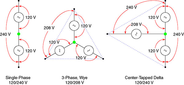
To the original poster, maybe this diagram might help you understand your question better. This is a diagram I created for another purpose, so it isn't specifically geared toward your question. The green dots represent the neutral in each system type.
SystemTypes-lo.jpg
 
Last edited:

mivey

Senior Member
Rick Christopherson said:
...With due respect, No. Real engineers do not look at this as a phase shift...[/IMG]

So engineers who look at it different than you are not "real" engineers? I'm impressed that you know all the "real" engineers and can speak for them. :roll:

Inductors and capacitors have long been referenced as causing a 90 degree PHASE SHIFT. In this case, you essentially are in the middle of two inductors, each causing a 90 degree phase shift for a total phase shift of 180 degrees.

iwire said:
I think it was a disservice to confuse him with additional subjective info that he does not need yet.

iwire,
It appeared rattus was mearly clarifying a point. pruter49 originally brought up the point that the voltages were 180 degrees out of phase. quogueelectric's response "The single phase xformer is not really 180 dg out of phase" appeared to refute that, even if that is not what he meant.

pruter49 was correct and it appeared rattus did not want quogueelectric's response to confuse him.

Of course I can't speak for rattus's intent, I'm just ASSUMING.

iwire said:
You are new here.....so you don't know how wrong that statement is. :grin:

It depends on ones point of view and reference.

I see what you mean
 

mivey

Senior Member
ronaldrc said:
Here we go again confusing Polarity with Phase. :D

Oh no. Was this a horse that has already been beat to death before? Please excuse me for stirring any old stink-pots.
 

mivey

Senior Member
mivey said:
Inductors and capacitors have long been referenced as causing a 90 degree PHASE SHIFT. In this case, you essentially are in the middle of two inductors, each causing a 90 degree phase shift for a total phase shift of 180 degrees.

I should have removed this as I typed before thinking but I'll leave it for honesty's sake.
 

rattus

Senior Member
Rick Christopherson said:
With due respect, No. Real engineers do not look at this as a phase shift. They put a minus sign in front of the voltage to signify that it is being referenced opposite from normal convention. Putting the voltage source out of phase changes the definition of the source:

V(t) = -V Sin(ωt)

versus

V(t) = V Sin(ωt + θ)

Mathematically they are the same, but an engineer is not going to change the phase. This is especially true because both "sources" are coming from the same transformer, with a center tap between them. "Out of phase" may be used in casual conversation, and I have used it frequently myself, but it is not the way an engineer would think about the sources.
=======================================


To the original poster, maybe this diagram might help you understand your question better. This is a diagram I created for another purpose, so it isn't specifically geared toward your question. The green dots represent the neutral in each system type.
SystemTypes-lo.jpg

First, engineers tend think in terms of phasors. Your diagram is not a phasor diagram. The voltages are provided as magnitudes only which is alright as far as it goes. In fact it is a rather nice diagram, except for the fact that delta systems do not carry a neutral.

Second, negating a phasor is exactly the same as specifying 180 degrees phase difference. It is nonsense to nit-pick this fact.

Third, the fact that V1 and V2 are taken from the same transformer is immaterial.

Fourth, since L1 and L2 share a common reference, it follows that V1 and V2 be defined relative to that reference--the neutral.

Fifth, if we observe V1 and V2 on a scope, relative to the neutral, we see a phase reversal. It is silly to claim otherwise. What you see is what you get.
 
Last edited:

Rick Christopherson

Senior Member
rattus said:
In fact it is a rather nice diagram, except for the fact that delta systems do not carry a neutral.
Really? :mad: So all those customers with an open delta system don't really have 120 volts available to them, it is just their imagination?
 

quogueelectric

Senior Member
Location
new york
Rick Christopherson said:
Really? :mad: So all those customers with an open delta system don't really have 120 volts available to them, it is just their imagination?
You took the words right out of my mouth. This is the first time a post of mine has been moved. Hanging around with the likes of Rattus what do I expect.
 

rattus

Senior Member
Rick Christopherson said:
Really? :mad: So all those customers with an open delta system don't really have 120 volts available to them, it is just their imagination?

Go find the definition of "neutral"!

If we are speaking only of the 120/240 subsystem, there is a neutral. If we are speaking of the entire delta system, there is no neutral.
 
Status
Not open for further replies.
Top