Battle of the Phases

Status
Not open for further replies.
coulter said:
Winnie - Maybe you are right, but I let me finish. Hang on just a little longer guys.


Rattus -

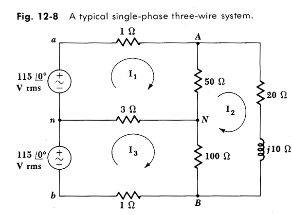
Just so I am clear: For single phase, you like the polarity marks with one at the centertap and one at the out side edge, and the arrows pointed away from each other?

carl

Carl, it is not what I like, it is the way the world, the US anyway, is wired. There is no choice in the matter.

Now since V1n and V2n are inverses of each other, the phasor arrows must point in opposite directions, and that is determined by one's choice of phase angle. Zero degrees is very onvenient; then we have 0 and 180 degrees. You can draw the schematic in any orientation you like, but the phasor arrows must be drawn according to the angles, with 0 degrees pointing due east.
 
Winnie,

Thanks Winnie for your support. That makes at least 5 who are in agreement in this matter. Even Carl is coming around--I think. Thanks also to wirenut and mivey and anyone else who agrees.

Let me emphasize that no one is being asked to change their methods. I doubt that you would anyway. Just consider this thread educational.

Now, I will set out to redefine "pi".
 
Plesae read up on "Logical Fallacy: Appeal to Belief". Even if 999 of 1000 people agree on something, it is not their majority that makes them right. It might just make them pompous and belittling, though. Why the constant scorecarding?
 
bcorbin said:
Plesae read up on "Logical Fallacy: Appeal to Belief". Even if 999 of 1000 people agree on something, it is not their majority that makes them right. It might just make them pompous and belittling, though. Why the constant scorecarding?

How about illogical fallacies? I am merely searching for the TRVTH. There is much misinformation in this world and I hope to correct a tiny bit of it.

I don't mean to belittle anyone. In fact, I use the phrase,'"with due respect", often. Frankly, I am mystified by your attitude. Now if you can prove me and the others wrong by a cogent argument, please do.
 
bcorbin said:
...It might just make them pompous and belittling, though.

pompous and belittling? what do you call this:

bcorbin said:
__________________
Proud to finally know how to spot a "real" Engineer.

[edit: I messed up the quote]

I see engineers go by on the train on a regular basis. I see a "reel" engineer when I go deep sea fishing :grin: .

Truly, I believe the term engineer gets stepped on a lot today by many industries but what are you going to do? I believe that there are some people who are engineers by experience even if they don't have an official degree. They make better engineers than some "real" engineers.

I would rather call someone an engineer who dedicates himself (herself?, themselves?, id-self?:mad: ...arrgh I hate political correctness at times) to the study of these type things than some of the the other people I have seen called engineers. How many "field engineers" have you seen that were not "real engineers". I know that some of these guys have spent more time in school than many ever will.

Get over it and focus on the content of what is said instead.
 
Power

Power

Don't forget Power guys. Voltage by itself does nothing.
Voltage Potential + Current Flow = Energy usage.

The Voltage waveforms when measured with neutral as the common point are mirror images. Current waveforms measured with respect to neutral are also mirror images.

Voltage waveform * Current waveform for either "leg" results in the EXACT SAME POWER WAVEFORM. (Neg * Neg = Positive)

Power in Same PHASE.

I staid at an ABET Holiday Inn.
 
rattus said:
Carl, please see the attached diagram. First we have the miswired transformer where identical voltages appear on L1 and L2. Since the voltages are equal in magnitude and phase, their phasors must be identical. Let V1n = 120 @ 0, then V2n = 120 @ 0. That is the arrows point in the same direction, and that direction is 0 degrees. This is not a matter of polarity marks.

Now consider the second diagram with a properly wired transformer. If V1n = 120 @ 0, then V2n = 120 @ 180. To find V12 or V21 we merely subtract one phasor from the other.
I really don't want to get in the middle of this single-phase two-phase argument, however, this is an incorrect use of phasors. You do not change the direction of a phasor when you change your reference point. Doing so violates Kirchoff's Voltage law, which states that the algebraic sum of the voltages around a closed path is equal to zero.

I don't care about the outcome of the rest of this argument, but you can't use phasors as part of its justification. The two phasors you drew in the top half of your picture are correct. The two opposing phasors you drew in the bottom half are incorrect.

This is all carefully spelled out in "Engineering Circuit Analysis", by Hayt and Kemmerly.
 
rattus said:
... Even Carl is coming around--I think. ...
Well, not yet. I've attached two pdfs.

The first is as I understand your model. I don't think it extends well -it just doesn't look right.

The second (This works.pdf) is the model I currently prefer (hey, tomorrow is a new day - quien sabe?) I think this one extends with little confusion.

carl
 
Nonsense:

Nonsense:

Rick Christopherson said:
I really don't want to get in the middle of this single-phase two-phase argument, however, this is an incorrect use of phasors. You do not change the direction of a phasor when you change your reference point. Doing so violates Kirchoff's Voltage law, which states that the algebraic sum of the voltages around a closed path is equal to zero.

I don't care about the outcome of the rest of this argument, but you can't use phasors as part of its justification. The two phasors you drew in the top half of your picture are correct. The two opposing phasors you drew in the bottom half are incorrect.

This is all carefully spelled out in "Engineering Circuit Analysis", by Hayt and Kemmerly.

I can't see tht Kirchoff has any bearing on this discussion. This is not a closed loop, phasors are complex numbers, so an algebraic sum does not apply anyway.

Fact is, one is free to define the phasors in EITHER direction. The phasor in question represents 120V @ 180. I could have reversed the arrow, then it would be 120V @ 0.

I was illustrating the point that these voltages are indeed 180 degrees apart. In that case, the arrows point away from each other. Indeed, this is a proper use of phasors.
 
rattus said:
I can't see tht Kirchoff has any bearing on this discussion.
:D :D :D Oh that is priceless! So does this mean we can ignore any laws that don't fit our needs at the moment?
rattus said:
This is not a closed loop,
Fine. Then close the loop and put a pair of resistors as loads, then try to apply Kirchoff's law
rattus said:
phasors are complex numbers, so an algebraic sum does not apply anyway.
You weren't paying attention in class. Kirchoff's Law(s) still apply to phasors.
rattus said:
Fact is, one is free to define the phasors in EITHER direction. The phasor in question represents 120V @ 180. I could have reversed the arrow, then it would be 120V @ 0.
The mistake you are making is that instead of redefining your reference point, you redefined the voltage source. This is a no-no.

At some instant in time, the upper voltage source will have (-) at the bottom and a (+) at the top. At the same instant in time, so will the lower power supply. This doesn't change, only your reference point changes.

rattus said:
I was illustrating the point that these voltages are indeed 180 degrees apart.
No, they are not 180 degrees apart, only your reference point makes it appear that they are.
 
Rick Christopherson said:
No, they are not 180 degrees apart, only your reference point makes it appear that they are.

Isn't the reference point one of THE points? Is that one reason we are having this discussion? I'm not saying we are actually moving electrons around or warping time by measuring from the neutral, only that our frame of reference changed.
 
I modified my previous drawing so you can see this clearer. Choose your words carefully, because your last posting was quite flawed, and this is an argument that is not open for people's opinions or interpretations. This is the basic core of circuit analysis.

SinglePhase.jpg
 
There you go again:

There you go again:

Rick Christopherson said:
:D :D :D Oh that is priceless! So does this mean we can ignore any laws that don't fit our needs at the moment?
Fine. Then close the loop and put a pair of resistors as loads, then try to apply Kirchoff's lawYou weren't paying attention in class. Kirchoff's Law(s) still apply to phasors.The mistake you are making is that instead of redefining your reference point, you redefined the voltage source. This is a no-no.

At some instant in time, the upper voltage source will have (-) at the bottom and a (+) at the top. At the same instant in time, so will the lower power supply. This doesn't change, only your reference point changes.

No, they are not 180 degrees apart, only your reference point makes it appear that they are.

Rick, you just don't get it do you? Go back and read Winnie's post on this matter.
 
Rick Christopherson said:
I modified my previous drawing so you can see this clearer. Choose your words carefully, because your last posting was quite flawed, and this is an argument that is not open for people's opinions or interpretations. This is the basic core of circuit analysis.

SinglePhase.jpg

Rick,

First, your arrows are vertical when they should be horizontal.

Second, you do not swap the leads on one of the sources. That would be the same as the miswired transformer.

Third, go back and read Winnie's post on the matter.

Fourth, tell me Winnie is wrong.
 
Last edited:
rattus said:
Rick, you just don't get it do you? Go back and read Winnie's post on this matter.
I don't care what winnie or anyone else said. You cannot throw away Kirchoff's law just because it doesn't suit you. Kirchof's Law doesn't care where your reference point is located. Apply Kirchoff's Law to your resulting circuit.

====================================================
NEW EDIT to the new edit Oh "shoot". I apologize. You did not edit your previous posting after I quoted you. I humbly apologize. After rereading this thread I noticed that you slipped in a new posting that I hadn't noticed earlier, and I thought you edited an existing post.

First off, no, there is nothing that forces these arrows to be horizontal. That is a matter of personal preference, not a dictate.

Secondly, I know you don't swap the leads of a power source, but that is my very point to begin with. When you defined this lower power supply to be 180 degrees out of phase with the other, that is exactly what you did!
 
Last edited:
Why is one person's frame of reference any more the most correct in the universe as compared to someone else's? In 100 years, the scientists of the day may be laughing at all of us.
 
mivey said:
Why is one person's frame of reference any more the most correct in the universe as compared to someone else's? In 100 years, the scientists of the day may be laughing at all of us.
It isn't about frame of reference. I am not disputing that a frame of reference can change. Rattus changed the definition of the source to meet his frame of reference, and that is something that you cannot do without violating Kirchoff's law.
 
mivey said:
Why is one person's frame of reference any more the most correct in the universe as compared to someone else's? In 100 years, the scientists of the day may be laughing at all of us.
Because we use mathematical models to predict real world phenomena. That's what we as engineers do. I would define the reference/model that gives the most accurate prediction as the "most correct".

Why would you think that 100 years from now scientists would be laughing at us? We are standing on the shoulders of the scientists 100 years before us - the same as the ones 100 years from now the next crew will be standing on our shoulders.

Are you laughing at the scientists 100 years ago? I'm not.

To the rest (not you mivey - I don't think you are doing this): When you get done with your peeing contest, which isn't particularly adding to the technical content, could I get a response on post 109. If I'm screwed up, I like to know why.

carl
 
coulter said:
When you get done with your peeing contest,...
No Carl, this isn't a peeing contest. I left that yesterday. This is about proper core circuit analysis, and what Rattus has done in this case is not proper.

I have scanned a page from "Engineering Circuit Analysis" that specifically discusses this very same situation. I am not arguing about "Single-Phase" "Two-Phase", and as a matter of fact Hayt and Kemmerly even acknowledge that this system can be called both. I do not have a dog in that hunt (to use Rattus' expressions).

What I am arguing about is the improper use of phasors to make this point. Note the polarity of the power sources. It does not matter if you change your point of reference. This polarity remains the same, and you use a minus sign in your equation. You do not redefine the power source.

3-wire-scan.jpg


NEW EDIT I apologize for editing this in the middle of a discussion, but it is better to note this here than to put it in a new posting.

From the diagram above, it is clear that the voltage from "n" to "b" is negative. However, if you had redefined that voltage source to be 115 @180 deg., then the voltage from "n" to "b" would suddenly become positive. If you were to do this and try to apply Kirchoff's law to this circuit, it would fail.
 
Last edited:
Status
Not open for further replies.
Top