Bonding Neutral in Transformer AND Panel

Merry Christmas
Status
Not open for further replies.

crossman

Senior Member
Location
Southeast Texas
This is from another thread but I believe it deserves its own thread. I want to know if I am thinking correctly.

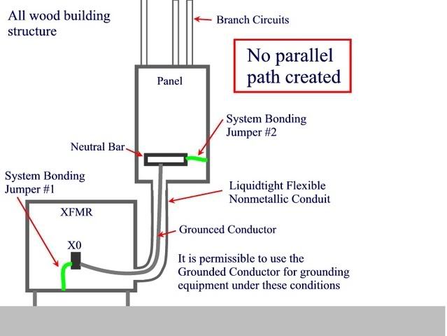
Given: A wood structure building, no waterpipe or structural steel. 480 3-phase service with ground rod as electrode. We are feeding a 480 to 208Y/120 xfmr. The transformer secondary feeds a panel with a main. All electrical equipment is mounted on the wood structure of the building.

250.30(A)(1) Ex 2 says we can put a system bonding jumper at the xfmr AND at the panel = bonding the neutral in 2 places if no parallel path is created.

250.142(A)(3) follows up and says we can use the grounded conductor (in this case, the neutral) for bonding between the source of the seperately derived system and the main disconnect.

So from that, I have the following diagram.

Do you see this as being what the NEC is saying, or am I missing something?

0011.jpg
 
Last edited:
Thank you.

Now, on that note, I am seeing a potentially hazardous situation here. If the neutral at the X0 terminal were to become disconnected or loose or badly corroded, then wouldn't the panel enclosure become energized in respect to the xfmr enclosure?

And if someone touched the xfmr enclosure and the panel enclosure, they could get shocked?
 
crossman said:
Thank you.

Now, on that note, I am seeing a potentially hazardous situation here. If the neutral at the X0 terminal were to become disconnected or loose or badly corroded, then wouldn't the panel enclosure become energized in respect to the xfmr enclosure?

And if someone touched the xfmr enclosure and the panel enclosure, they could get shocked?
There would be a potential difference & shock hazard because the system is not likely to be balanced. I guess we could speculate as to the severity of the imbalance.

[edit: how many grounding electrodes & locations are present in your scenario?]
 
Last edited:
As for grounding electrodes, both the 480 service and the xfmr X0 are connected to driven grounds which are connected together.

Edit to add: I don't think the grounding electrodes would do anything to mitigate the hazard.
 
Last edited:
mivey said:
There would be a potential difference & shock hazard because the system is not likely to be balanced. I guess we could speculate as to the severity of the imbalance.

I wonder why the NEC panel still allows this, considering all the other restrictions they have placed on similar scenarios, such as second buildings.
 
crossman said:
Thank you.

Now, on that note, I am seeing a potentially hazardous situation here. If the neutral at the X0 terminal were to become disconnected or loose or badly corroded, then wouldn't the panel enclosure become energized in respect to the xfmr enclosure?

And if someone touched the xfmr enclosure and the panel enclosure, they could get shocked?

Sure looks like so, but wouldn't that be a far reach if that is the utility xfmr? I didn't see a SE meter main disco in the diagram which would change the bonding requirements to the Xfmr case, wouldn't it? rbj
 
The wood frame building doesnt have any conductive metal parts. My question is what about between SDS and Load side equipment? FMC? Same question you asked crossman....I agree.
 
Last edited:
Being a Canuk I'm not an expert on the NEC so take this with a grain of salt:

I suspect that 250.30(A)(1) Ex 2 is there to provide the shortest possible path for any fault currents between the transformer windings and enclosure, i.e. if a worker accidentally got a pitchfork tine into a transformer and shorted a phase to the enclosure (don't ask how I know this), and not to eliminate the need for a continuously bonded raceway between the two enclosures.

Isn't there a separate code requirement to pull a bonding conductor into all non-metallic sealtite to ensure the continuity of the bond?

Edited for clarity.
 
Last edited:
gndrod said:
Sure looks like so, but wouldn't that be a far reach if that is the utility xfmr? I didn't see a SE meter main disco in the diagram which would change the bonding requirements to the Xfmr case, wouldn't it? rbj

Okay, let me rephrase since it wan't clear:

There is a 480 volt service on the wooden building. There is a 3-pole breaker in the 480 volt panel which feeds the primary of the xfmr. None of this is shown in the drawing.

The secondary of the xfmr feeds the 208Y/120 panel located near the xfmr as shown in the drawing.

A loose neutral at X0 would cause the panel enclosure to be energized and because it is in close proximity to the xfmr, we could certainly touch both items at the same time.
 
crossman said:
I wonder why the NEC panel still allows this, considering all the other restrictions they have placed on similar scenarios, such as second buildings.

I was thinking an application of this rule would be a facility that distributes power at high voltage around their property and then has pad mounts at each building.

Typically you would bond at the pad mount and at the feeder entrance disconnect.
 
Last edited:
crossman said:
Okay, let me rephrase since it wan't clear:

There is a 480 volt service on the wooden building. There is a 3-pole breaker in the 480 volt panel which feeds the primary of the xfmr. None of this is shown in the drawing.

The secondary of the xfmr feeds the 208Y/120 panel located near the xfmr as shown in the drawing.

A loose neutral at X0 would cause the panel enclosure to be energized and because it is in close proximity to the xfmr, we could certainly touch both items at the same time.

I think I get it. So this is a feeder that requires a separate EGC between enclosures? The panel shown is the main feeding the Xfmr without an EGC system jumper even though the panel has a main bonding jumper. Can this be what is happening? Sorry for me playing a confusion card, generally schematic diagrams show circuit flow left to right, top to bottom.
 
iwire said:
I was thinking an application of this rule would be a facility that distributes power at high voltage around their property and then has pad mounts at each building.

Typically you would bond at the pad mount and at the feeder entrance disconnect.

That could be so. But it still seems that what is shown in my drawing would be legal but could lead to a hazardous situation, and could even be as bad as or worse than "the children" sticking knives into a duplex receptacle in their residential hallway.:roll:


Edit: correct typo
 
Last edited:
gndrod said:
I think I get it. So this is a feeder that requires a separate EGC between enclosures? The panel shown is the main feeding the Xfmr without an EGC system jumper even though the panel has a main bonding jumper. Can this be what is happening? Sorry for me playing a confusion card, generally schematic diagrams show circuit flow left to right, top to bottom.

None of the 480 volt service or primary feed is shown. All I am showing is the secondary side X0 and the grounded conductor to the panel which which is being fed from the xfmr secondary.
 
Saddle on backwards today

Saddle on backwards today

crossman said:
None of the 480 volt service or primary feed is shown. All I am showing is the secondary side X0 and the grounded conductor to the panel which which is being fed from the xfmr secondary.

Thanks for being patient. I missed "seperately derived system'" and now I see what you are saying. Tx, rbj
 
Status
Not open for further replies.
Top