Just what does, "design electrical resistivity equipment" mean?
Our team has developed the Electrical Resistivity Imaging technique in 1992 by automating a well known method developed originally by the Schlumberger brothers in 1913. At that time a volt meter and electric field generator was used to manually make measurements. We automated the data collection process in 1992 and later developed the 3D visualization software for modeling the collected data as the personal computer became more powerful and was capable of calculating a small amount of data within in minutes rather than days and as Windows 95 made working with computers more friendly.
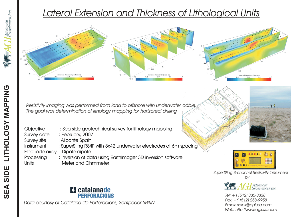
Electrical Resistivity Imaging equipment is an imaging technique used to create a 3D scan of a material (usually into the Earth's subsurface). Electrical resistivity is a bulk electrical property of all material. It is a measure of how well a material resists the flow of electricity. In our application we deal strictly with DC.
Most people are familiar with MRI's that are used by medical doctors to image a patients body. A well known relations ship between magnetic fields and the magnetic moment of the proton in Hydrogen. This is the property determined when using MRI's.
In our case we create a static electric field by injecting (transmitting) DC into the subsurface through two electrodes hammered into the ground. A static electric field, if visible would show the current density of the electricity passing from one electrode to the other electrode. Think of an onion cut into two halves where the shells of the onion represents the electric field.
The electricity will flow everywhere in the material, however it will want to flow more (more current density) through conductive mediums and less in resistive (less current density) mediums. During the time the electricity is injected we measure the potential field. The potential field is like a map of voltage. You could stick the two probes of a volt meter into the ground and measure some voltage. This is actually what our equipment does but it does it automatically and very quickly at many thousands of combinations of current injection locations and voltage measurements.
In a homogeneous material (a material with the same resistivity property) the electric field will be uniform and un-distorted like the onion shells. Now lets think of one of the most intuitive cases our equipment is used, exploring for tunnels and caves. Imagine that we place an air filled cave in the middle of our homogeneous subsurface. Since air is very resistive at low voltages the electricity will have to "go around" the cave. This creates a distortion of the electric field. We measure these distortions at the surface and/or in boreholes. In order to properly define these distortions we have to make many thousands of measurements.
Back to the imaging part...in order to create a 3D model of the ground we use computers to perform all the dirty work for us. This particular step involves solving lots of non-linear equations in a smart way using. The mathematical approach is called Finite Element computation. To make things more difficult, it turns out that the data (volt measurements) we collect can be reproduced with an infinite number of computer models. We then use some statistical norms to narrow down the solution that fits our data but not so well that it incorporates the inherent noise in our hardware, software, computer rounding errors, telluric noise from the Earth's electric storms, Magneto-telluric noise from our Sun's interaction with our Earth's magnetic field, streaming potentials due to moving fluids in the ground, self potential due to acid rain oxidation of minerals, and positional errors we have made hammering the electrodes in the ground at a grid.
Some of the uses for Electrical Resistivity Imaging by industry:
Geotechnical: finding electrical properties of sub-surface, grounding grid evaluation (IEEE Fall of potential and ASTM G57)
Geophysics: exploration for water, mineral deposits, pollution, geologic features
Archeology: determine where to dig, find artifacts, looking for treasure (really), image pyramids, catacombs, burial sites
Civil engineering: locate old mine shafts, find sink holes, locate competent ground to build on, define aggregate deposits for road and infrastructure, dredge channels, determine weakness' in levy's
Mining: locating ore deposits, provide safety for mine workers by monitoring water flow into mine, coal mining, leach pad imaging
Petroleum: locate and re-mediate spills, maintaining drilling collection ponds, some shallow oil exploration has been done but it really isn't useful for this since oil is usually too deep for us to image
Military applications: looking for prison tunnels, mass graves
Environmental: image pollution plumes, locate pockets of pollutants, finding DNAPL (chlorinated solvents like Creosote)
Our website has lots of case histories:
www.agiusa.com
