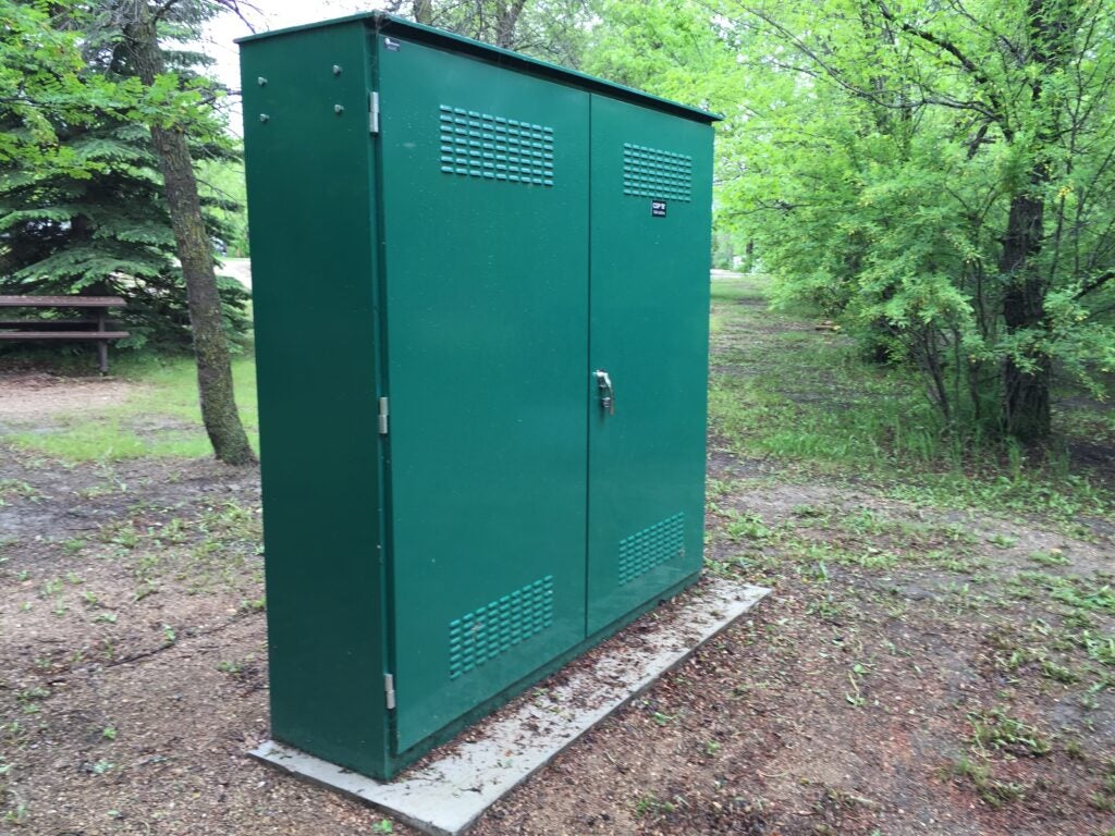
Buried PVC conduit and direction changes

Status
Not open for further replies.

rsteph5

Member
Location
Indiana
Occupation
Electrical Engineer
Hello,
I am working on the electrical design for a new RV park. The park is 30 sites with 50A services going to each. The park will divided into four separate regions that each have a 400A electrical service with the distribution panel centrally located in region to minimize voltage drop.
The 400A distribution panel has knockouts for up to (4) 3in conduits. Using #2 THHN conductors, I could put 2 circuits in each conduit to go from the panel to the pedestals.
My question lies here: how can I branch from the conduit to allow the first circuit to exit to its pedestal while allowing the remaining circuit to reach its pedestal?
My first thought was to use a tee type conduit body, but I’ve gotten mixed feedback for using that in a buried scenario. We’re planning to use schedule 40 conduit.
my experience is primarily in electrical substations where we use board trench and only use conduit where a circuit leaves the trench so I am not familiar with longer runs of conduit. Thanks for any info.
 
Welcome to the forum.

How about a PVC pull box under each first pedestal? Stub up from the panel, stub back down to the next pedestal, and nipple up to this pedestal.
 
Thanks for the reply. I do feel I should clarify since I left it out that each circuit would be on its own breaker.
So you’re saying to to bring both circuits into the pull box and then terminate one circuit at the pedestal while sending the other circuit back down the second conduit stub up. Then go go over to the next pedestal? I like the sound of that method. Would the pull box be able to be completely buried?
 
You're also using large conductors, so you need to have 6X the conduit diameter for an angle pull and 8X for straight. Going to need a huge T condulet to do that (maybe a 3" one if using 1.5" conduit)? You have the same issue with a pull box. That isn't a problem, just a large ugly box, especially if the conduit is large.

Can you bury condulet fittings in the dirt? I assumed no, but couldn't find a code rule for that.
 
So you’re saying to to bring both circuits into the pull box and then terminate one circuit at the pedestal while sending the other circuit back down the second conduit stub up. Then go go over to the next pedestal? I like the sound of that method. Would the pull box be able to be completely buried?
I envision a 4x4 post with the box being attached to it just above ground, mounted like you would on a wall.

Unless you can bring both conduits into the pedestal itself. I'd have to see what you're using to comment further.
 
What is the concern here?
I did not have a concern with it as that is what I thought those were for. However, some electrician/electrical designers I have mentioned that idea too have acted like that is not their intended purpose. They didn't elaborate much so I am not sure why they didn't like it. I couldn't find anything in the NEC that says condulets cannot be direct buried. Are you familiar with buried condulet boxes?
 
The demand factor for 30 sites is 42%. That’s 151.2kva if all are 50A pedestals. You sure 400A is adequate?

Edit…. Sorry just realized you said each of the 4 areas has a 400A MDP.


Have you looked at the Valid Manufacturing distribution centers? I’m currently working on a design for an RV park and had them quote the project.


Sent from my iPhone using Tapatalk
 
The demand factor for 30 sites is 42%. That’s 151.2kva if all are 50A pedestals. You sure 400A is adequate?


Sent from my iPhone using Tapatalk
The 30 sites will be divided into 4 regions (8 50A sites on the front two regions and 7 on the 2 back regions) and each region will be getting a 400A service. Each region will also have a 75KVA transformer from the local utility so in total the whole park will be able to use up to 300KVA. My client is mainly catering towards large RVs so we decided that the demand factor would not be adequate for the park especially in the summertime. It is unlikely that each site will always be booked, but he wanted to be prepared for the hot weeks like we're experiencing in Indiana right now.
 
Just a thought: can two pedestals share one feeder? :unsure: Or would it be better to avoid doing that?
You can have pedestals share feeders and it is a fairly popular method. Most RV pedestals have loop thru lugs on them for this very purpose. We're trying a something at this site that prevents us from sharing feeders. We're actually installing Eaton smart breakers for each feeder at the main distribution panel to provide wireless metering and the ability to remotely turn off pedestals to prevent use of neighboring sites when not rented out. There will still be a regular breakers at the pedestals for local disconnect and protection. I am very excited to see how it turns out.
 
Then I'm still at looping through each first pedestal to each second one.

Will there be any "house-panel" loads, like site lighting, office, store, etc?
 
The pedestals can handle up to (3) 2.5in conduits so I like your idea. You don’t see any issues with cable bend required to go from one conduit stub up to the next? I am actually using #6 THHN and not #2 as I previously said. I had a typo in the original post.
And yes there will be some house panel loads. Dump station, sewer, and some stuff like that. The big house panel draw will be the building that houses the IT equipment. I am planning to feed that off of one of the panels currently. Once they get all the load info to me I’ll make the decision as to whether the transformer in that area of the park will need to be upsized.
 
The project does sound exciting. Wife & I stayed frequently at an older campsite that had 30 amp pedestals, but many RVs on same circuit. Horrible.
But... some of the new big RVs have dual ACs, some electric fireplaces, crazy.
Wonder if the 50 amp would service those.
Nice project!
 
The pedestals can handle up to (3) 2.5in conduits so I like your idea. You don’t see any issues with cable bend required to go from one conduit stub up to the next? I am actually using #6 THHN and not #2 as I previously said. I had a typo in the original post.
No, especially with #6.

And yes there will be some house panel loads. Dump station, sewer, and some stuff like that. The big house panel draw will be the building that houses the IT equipment. I am planning to feed that off of one of the panels currently.
Instead of dividing the feeders into 8, 8, 7, and 7, make it 8, 8, 8, and 6, leaving more capacity for the house panel.
 
You can have pedestals share feeders and it is a fairly popular method. Most RV pedestals have loop thru lugs on them for this very purpose. We're trying a something at this site that prevents us from sharing feeders. We're actually installing Eaton smart breakers for each feeder at the main distribution panel to provide wireless metering and the ability to remotely turn off pedestals to prevent use of neighboring sites when not rented out. There will still be a regular breakers at the pedestals for local disconnect and protection. I am very excited to see how it turns out.

Wait a minute.

This is exactly the project I’m in design phase on lol.

Eaton told me the breakers are 20/wks out. I need about 400 of them though (multiple sites) and they told me probably much longer for that amount.

Where are you located? Maybe we should talk.

I’m pretty sure we aren’t working with the same client because I haven’t submitted any of the designs yet showing the Eaton breakers.


Sent from my iPhone using Tapatalk
 
Status
Not open for further replies.
Top