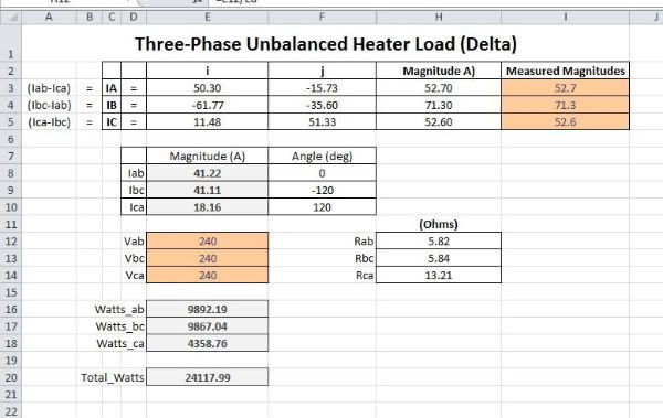
Seems like one load is shorted.
Assuming 58 A line current at zero degrees, 58/0
and 76 A line current at 120 degrees, 76/120
and assuming a fault in only one of three loads [Ra, Rb, Rc]
which means Rb = Rc
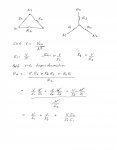
then 58/0 = (1/Ra)240/0 - (1/Rb)240/120
and 76/120 = (1/Rb)240/120 -(1/Rb)240/240
I get Rb = Rc = 5.47 ohms and then Ra = 0.18 ohm.
If I made no mistakes in going from polar to rectangular and back again, this should be right.
In any case, with the formulas and assumptions stated above, this can be checked.
I'm out of here. . .
Assuming 58 A line current at zero degrees, 58/0
and 76 A line current at 120 degrees, 76/120
and assuming a fault in only one of three loads [Ra, Rb, Rc]
which means Rb = Rc
then 58/0 = (1/Ra)240/0 - (1/Rb)240/120
and 76/120 = (1/Rb)240/120 -(1/Rb)240/240
I get Rb = Rc = 5.47 ohms and then Ra = 0.18 ohm.
If I made no mistakes in going from polar to rectangular and back again, this should be right.
In any case, with the formulas and assumptions stated above, this can be checked.
I'm out of here. . .
Last edited:

") (Differentiate the two functions then divide them - I didn't look it up, is that close to right?)
(Differentiate the two functions then divide them - I didn't look it up, is that close to right?)