Calculating Phase Currents Based on Measured Line Currents - Delta Heater Load

Status
Not open for further replies.

Smart $

Esteemed Member
Location
Ohio
I agree that your geometric solution would be the way to go. Solving 3 simultaneous equations with 4 unknowns would be too much math for me.

However, I think your method led you astray somewhere. For the values of Iab, Ibc, and Ica that you list above, I come up with:

Ia=101.85<0.51
Ib=110.48<-117.5
Ic=109.50<117.6

Probably just a add/subtract error somewhere.
For the values you get, probably a combination of compounded rounding errors, in your initial values, my results, and then again in your verification.

To demonstrate, your initial values are:
Ia=102.37<0
Ib=110.48<-118.56
Ic=108.96<117.04​
If we leave the magnitudes of all three and the angle of Ia as exact, the angle of Ib has to be -118.557631364? while the angle of Ic has to be -242.9474265101? (same as +117.0525734899?) with accuracy carried to 10 decimal places, in order for the three vectors to form a triangle. As stated, the vectors given placed head to tail would form an open polygon. There would be a gap between the last head and the first tail. Correcting the angles for the errors is how I chose to proceed as it was the easiest means. If I chose the more difficult compensation, i.e. proportionally distributing the rounding errors to all five [variable*] values, the verification would have been closer to your initial values.

*Since angles are relative, Ia would remain as 0?
 

gar

Senior Member
Location
Ann Arbor, Michigan
Occupation
EE
110125-1518 EST

jakeself:

By implication your SCR controller has 3 input terminals and 3 output terminals. There are various modes. Full cycle on occurs on positive zero crossing, but missing N full cycles between the on cycles, where N is controllable from 0 to some maximum (this is not possible on zero crossing with 3 output terminals in a delta mode -- i did not totally read the instructions); phase shift control is another mode; and always fully on or off. What mode are you using?

Why can't you put your monitoring meter on a wire to a resistance bank and directly measure the current in the bank? Such a wire must exist or could be made to exist. Avoid this attempt to deduce bank currents from line currents as I suggested in some earlier post, and as Open Neutral has just suggested.

.
 

Smart $

Esteemed Member
Location
Ohio
...

I am only able to measure line current RMS magnitude. (not phase angles).

...
Just curious as to why you cannot place your "sensors" to measure the phase current. I'm currently picturing a control cabinet with your PLC and controllers, with heaters located remote to the cabinet... and your sensors are in-cabinet. If you wanted to keep the sensors in-cabinet, is it possible to run six conductors to the heaters. Technically you would only need five conductors—one would be a line conductor while the other four would be phase conductors, with sensors on three of those—but that might be confusing for many :D

BTW, for sensors, I'm picturing something like the AcuAMP ACTR series.
 
Last edited:

david luchini

Moderator
Staff member
Location
Connecticut
Occupation
Engineer
For the values you get, probably a combination of compounded rounding errors, in your initial values, my results, and then again in your verification.

To demonstrate, your initial values are:
Ia=102.37<0
Ib=110.48<-118.56
Ic=108.96<117.04​
If we leave the magnitudes of all three and the angle of Ia as exact, the angle of Ib has to be -118.557631364? while the angle of Ic has to be -242.9474265101? (same as +117.0525734899?) with accuracy carried to 10 decimal places, in order for the three vectors to form a triangle. As stated, the vectors given placed head to tail would form an open polygon. There would be a gap between the last head and the first tail. Correcting the angles for the errors is how I chose to proceed as it was the easiest means. If I chose the more difficult compensation, i.e. proportionally distributing the rounding errors to all five [variable*] values, the verification would have been closer to your initial values.

*Since angles are relative, Ia would remain as 0?
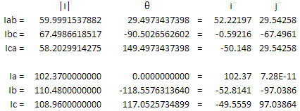
I don't think its a rounding error. You have the magnitudes exactly as I would have expected them, and the Ica angle exactly as expected. But the Iab and Ibc are off by exactly 1 degree. This doesn't sound like a problem in rounding.

I drew up the geometric form as you noted, with the angles to 10 decimal places, and come up with Iab=60<29.5, Ibc=67.5<-90.5, Ica=58.2<149.5, just as I would have expected.

At one point I was measuring Ibc and had an angle of 89.5. I thought to myself that is one degree off, just like in your solution. Then I realized it wasn't one degree off, it was 180 degrees off, and was giving me the the exact value I expected (-90.5.) I think this is how you arrived at -89.5 for Ibc. I don't know how you got 30.5 for Iab instead of 29.5, however.
 

Smart $

Esteemed Member
Location
Ohio
I don't think its a rounding error. You have the magnitudes exactly as I would have expected them, and the Ica angle exactly as expected. But the Iab and Ibc are off by exactly 1 degree. This doesn't sound like a problem in rounding.

I drew up the geometric form as you noted, with the angles to 10 decimal places, and come up with Iab=60<29.5, Ibc=67.5<-90.5, Ica=58.2<149.5, just as I would have expected.

At one point I was measuring Ibc and had an angle of 89.5. I thought to myself that is one degree off, just like in your solution. Then I realized it wasn't one degree off, it was 180 degrees off, and was giving me the the exact value I expected (-90.5.) I think this is how you arrived at -89.5 for Ibc. I don't know how you got 30.5 for Iab instead of 29.5, however.
You are correct. :mad:
Rechecked everything... 30.5 was a math error on my part... and the -89.5 was an app error. Final confirmed-accurate numbers and back-solve verification...

numbers.gif


Ultimately, the method is fine as long as implemented within its limitations (and accounting for mine ;)).
 
Last edited:

jakeself

Member
110125-1518 EST
jakeself:
By implication your SCR controller has 3 input terminals and 3 output terminals. There are various modes. Full cycle on occurs on positive zero crossing, but missing N full cycles between the on cycles, where N is controllable from 0 to some maximum (this is not possible on zero crossing with 3 output terminals in a delta mode -- i did not totally read the instructions); phase shift control is another mode; and always fully on or off. What mode are you using?

Why can't you put your monitoring meter on a wire to a resistance bank and directly measure the current in the bank? Such a wire must exist or could be made to exist. Avoid this attempt to deduce bank currents from line currents as I suggested in some earlier post, and as Open Neutral has just suggested.
.

I believe based on the "C0" in the part number, the SCR is always fully ON or OFF because the input control is just a 24VDC signal.

Part of the problem with putting the current sensors to directly measure the phase currents in the banks is that the SCRs and future CTs are in the control cabinet. The SCRs have a 3-conductor cable out to a junction box near the heating elements (not near the control cabinet). At that point, the branches are created to form the multiple heating banks between phases. I will look at the possibility of getting directly on the individual banks, but the installation of the CTs will be much more difficult. This may be AN option if I cannot figure out how to do it otherwise. I will upload a schematic of a couple of the heater layouts tomorrow.
 

Smart $

Esteemed Member
Location
Ohio
I stated in post #63
... If you wanted to keep the sensors in-cabinet, is it possible to run six conductors to the heaters. Technically you would only need five conductors?one would be a line conductor while the other four would be phase conductors, with sensors on three of those?but that might be confusing for many :D...

Posts #66 -68
...

Part of the problem with putting the current sensors to directly measure the phase currents in the banks is that the SCRs and future CTs are in the control cabinet. The SCRs have a 3-conductor cable out to a junction box near the heating elements (not near the control cabinet). At that point, the branches are created to form the multiple heating banks between phases. I will look at the possibility of getting directly on the individual banks, but the installation of the CTs will be much more difficult. This may be AN option if I cannot figure out how to do it otherwise. I will upload a schematic of a couple of the heater layouts tomorrow.

110125-2245 EST

Run another 3 conductor cable to the heater banks, or better two 2 conductor cables to get the 6 needed wires.

.

110125-2327 EST

Actually a total of 5 wires to the load banks is sufficient to allow direct current measurements in the control panel.

.
Is there an echo in here???
 
Last edited:

jakeself

Member
We will be rewiring the machine to take 6 leads out to the ovens, then branching off to create the heater banks. I see that would could have used 5 leads, but 6 was just as easy to run. No more worry about conversions and current will be directly known for each bank within the PLC.

Thanks!
 

Smart $

Esteemed Member
Location
Ohio
We will be rewiring the machine to take 6 leads out to the ovens, then branching off to create the heater banks. I see that would could have used 5 leads, but 6 was just as easy to run. No more worry about conversions and current will be directly known for each bank within the PLC.

Thanks!
...and it only took 70 posts to get there :cool:
 

mivey

Senior Member
I think its a bit more difficult than just vector math.
I'm thinking it is not. Of course, it would not be the first time I have been wrong. ;)

The line current angles must be referenced to the voltage angles. That is, we must also know the voltage angles, then we would know the value of theta. Still a messy problem to solve.
You could reference to a voltage but these are resistive loads so ...

David, I am saying that the measured line current angles must be referenced to something, and that something must be a voltage angle.
Why not just measure the current waveforms and let one of them be the reference?
 

mivey

Senior Member
David....

The calculation basis changed when mivey responded to jakeself's statement that he had some metering class CT's ordered. I believe the assumption was made that line-line voltage was/is also being measured and angles (phase relationship) determined.
That was my first thought since these voltages are readily available but after I thought about it, I wondered why we couldn't just use the current vectors?
OK, let me try it this way...If I measure the line currents of an unbalanced, delta connected, resistive load and tell you that the currents are as follows:

Ia=102.37<0
Ib=110.48<-118.56
Ic=108.96<117.04

What is the phase current angle of Iab? I don't even want to know the magnitude of Iab. Just the angle. How are you going to determine the angle of Iab with only the information I have given you? As far as I can tell, that angle is an unknown.

You cannot arbitrarily assign an angle of zero to one of the L-L voltages. In this example, you would have Vab at angle zero, Iab at angle zero, and Ia at angle zero. This is not possible.
How about with a symmetrical component transformation? I may not have thought this through enough as my work lately has been an exercise in sleep deprivation, but here is what I'm thinking:
Transform the unbalanced set of line currents into a balanced set of positive and negative sequence components, convert those to component phase currents, then transform back those into the phase currents.
 

mivey

Senior Member
We will be rewiring the machine to take 6 leads out to the ovens, then branching off to create the heater banks.
That seems like the easiest solution from one perspective but not near as much fun from an engineering standpoint. ;)

....Not that I wouldn't still like to know the equations to do what I was asking. :cool:
Here is what I got:
Measuring the vectors Ia, Ib, Ic (using Smart $'s OCD decimal places ;))
Ia = 102.37@0?
Ib = 110.48@-118.557631364?
Ic = 108.96@117.052573490?

then (the "a" operator is 1@120?):

Ia0 = 1/3*(Ia+Ib+Ic)
Ia1 = 1/3*(Ia+a*Ib+a^2*Ic)
Ia2 = 1/3*(Ia+a^2*Ib+a*Ic)

then:

Idelta0 = Iao
Idelta1 = Ia1/sqrt(3)*1<30
Idelta2 = Ia2/sqrt(3)*1<-30

then:

Iab = Idelta0+Idelta1+Idelta2
Ibc = Idelta0+a^2*Idelta1+a*Idelta2
Ica = Idelta0+a*Idelta1+a^2*Idelta2

with the following results:

Iab = 61.008754381@32.018273242?
Ibc = 64.701543087@-90.961820028?
Ica = 60.090641349@147.432667582?

and the check produces:

Iab-Ica = Ia = 102.370000000@0.000000000?
Ibc-Iab = Ib = 110.480000000@-118.557631364?
Ica-Ibc = Ic = 108.960000000@117.052573490?
 

mivey

Senior Member
Here is what I got:
For those that want the intermediate values:
Ia0 = 0.000000000@-74.206255105?
Ia1 = 107.214410949@-0.502656260?
Ia2 = 4.930826656@169.003141576?

Idelta0 = 0.000000000@-74.206255105?
Idelta1 = 61.900269022@29.497343740?
Idelta2 = 2.846814097@139.003141576?
 

rattus

Senior Member
Because!

Because!

I'm thinking it is not. Of course, it would not be the first time I have been wrong. ;)

You could reference to a voltage but these are resistive loads so ...

Why not just measure the current waveforms and let one of them be the reference?

The choice of reference is arbitrary, but we still must know the relationship between the load current angles and the line current angles. The load current angles would equal the load voltage angles, so it is convenient to let Vab be at angle zero, then Iab would also be at angle zero, etc. All other angles would be measured relative to Vab or whatever you choose.
 

mivey

Senior Member
The choice of reference is arbitrary, but we still must know the relationship between the load current angles and the line current angles. The load current angles would equal the load voltage angles, so it is convenient to let Vab be at angle zero, then Iab would also be at angle zero, etc. All other angles would be measured relative to Vab or whatever you choose.
Yeah, I'm missing something but am too tired to figure out what I'm doing. I ran another scenario and it did not come out right. I'll post my numbers in case someone feels froggy enough to look at it. I've got a plane to catch.:
Begin with phase voltages, just a little unbalnced for fun:
Vab = 482.000000000<0.000000000?
Vbc = 479.000000000<-121.000000000?
Vca = 473.226244709<119.816136066?

Some example phase loads:
Rab = 12 ohms
Rbc = 8 ohms
Rca = 4.8 ohms

Phase currents:
Iab = 40.166666667<0.000000000?
Ibc = 59.875000000<-121.000000000?
Ica = 98.588800981<119.816136066?

Line currents:
Ia = 123.576152816<-43.803702128?
Ib = 87.611006252<-144.140179271?
Ic = 138.063536773<97.567541062?

Line currents with phase a reference:
Ia = 123.576152816<0.000000000?
Ib = 87.611006252<-100.336477143?
Ic = 138.063536773<141.371243189?

Sequence components:
Ia0 = 0.000000000<71.565051177?
Ia1 = 114.676489345<13.411006012?
Ia2 = 29.190195399<-65.668654654?

To delta:
Idelta0 = 0.000000000<71.565051177?
Idelta1 = 66.208501993<43.411006012?
Idelta2 = 16.852967172<-95.668654654?

Back to phase currents:
Iab = 54.601554451<31.747068464?
Ibc = 65.152293096<-61.875470865?
Ica = 82.320189940<159.573854784?

Then line currents:
Ia = 123.576152816<0.000000000?
Ib = 87.611006252<-100.336477143?
Ic = 138.063536773<141.371243189?

The line currents were fine but the phase currents were different. Maybe multiple solutions? I'm out of time so I'll have to worry with it later.

Have fun.
 

Smart $

Esteemed Member
Location
Ohio
...
with the following results:

Iab = 61.008754381@32.018273242?
Ibc = 64.701543087@-90.961820028?
Ica = 60.090641349@147.432667582?

...
Your result has relative phase angles of:
122.980093270?
121.605512390?
115.414394340?
They should be 120? apart with purely resistive loads. Since they are not, this is indicative the magnitudes are in error also.
 
Status
Not open for further replies.
Top