Thanks all, this was all very interesting.
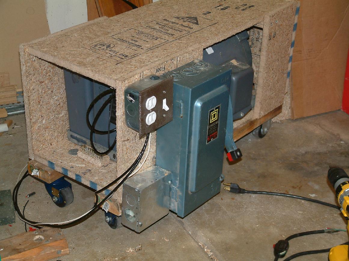
So is my understanding correct, single phase L1 and L2 looked to be carried through and the converter actually generates a L3( image from
@MTW ). And it seem from the one linked info that Larry gave it shifts the phase a little to put them at 120 deg from each other. It also stated that this way of getting 3 phase was the more
stable means compared to straight capacitor use. (Brings up question below)
So
@Jraef this way of getting 3ph is actually using a 3phase motor inline to get the 3rd of a 3ph system? That is why I got wondering about it because that is what they look like, just a big motor, but it was getting 3ph output. It seems you could make one yourself out of a 3ph motor.
I've got a customer I've put power cords on some of his new woodworking equipment for him that the mfg install sheet indicated that the motors could be hooked up either by 1ph or 3ph and gave instructions of the connections and where to alter one of the internal connectors. He bought them pre set as a 1ph so my cord connection was simple red-red, black-black, green-green. No neutral connections.
So likely with these peices of equipment they are using a capacitor to "trick" the 3ph motor into spinning on 1ph. (Wow so devious, lol)
This brings up a question, this same customer has had some power issues when using his larger equipment. I'm going to assume they are the same type of motors as I just wired (3ph motor on 1ph supply). When any of these larger motor start there is a momentary flucuation in the power level of the system, but not consistent as to intensity or which phase (L1 or L2)on same motor. Could this be caused by the motors need for or ability to use 3 phase and the capacitor that shifts the phases? It does balance back out once motor starts. But the phenomenon lasts long enough to capture on a standard volt meter though. He wants to install led lighting in the shop so I wonder if this will become a more noticeable issue on the led vs his current fluorescents? I've seen issues with led and poor power quality.
Also, he is planning expanding his shop and with more equipment too. So would he be well served by getting one of these phase converters and using these tools on 3ph? Would that reduce the likelihood of needing to increase the system size all the way back to the utility? I know 3 ph uses a fraction the power as 1ph for the same hp motor (info from spec sheets not experience).