correct grounding

Status
Not open for further replies.
Lxnxjxhx said:
No, but I did electronics work.

With equipment that had sensitive inputs driving several watts of power on the output we had to worry about single point grounds, but that was it.

We don't have the equivalent of the NEC, so I guess we did a lot more testing. At least I did.
In most cases, anything with that much power is not going to care about grounding that much, at least as far as signal integrity goes.
 
Katessa Harris said:
In a house that is not new construction, is there a way to tell if it has been properly grounded?

The ground is defined and is the earth connection for lightning and over-voltages 250-4(A)(1), it is not the ground fault path for shorts, but at a minimum I recommend the following.

First:
  • locate a qualified electrode 250-52
  • locate and qualify the grounding electrode conductor and it's connection 250-24, 250-64, 250-66
  • qualify to correct separation of neutral from ground bonding past the service disconnect 250-24(A)(5), 250-142(B), this must be separate to avoid a parallel neutral return path.

Bonding (like 250-102) is extremely important as this is the effective ground fault path for shorts, in other words all shorts are trying to return to their source which is usually the XO of a service transformer
  • locate and qualify the neutral bond at the service disconnect, this neutral (grounded conductor) serves as a duel purpose in that 1) it is the return path for the unbalanced load & 2) it is the ground fault path to source for shorts, 250-24.
  • locate and qualify water bond, 250-104(A)
  • locate and qualify other metal piping bonds, 250-104(B)
  • qualify all down-stream ground fault paths (bonding)
The bonding is what determines an effective ground fault path (lowest resistance possible), and this path is what allows the highest amperes possible to open any circuit in a fault.
 
brian john said:
Yes it is wrong, because the average electrician is not going to perform the test properly so the results are meaningless.

Do you perform earth ground resistance test?

You may very well be right (my objective is to learn
something here, I have been embarrasingly wrong
several times on the forum), but my understanding of why this
test wasn't a good use of time is that it is highly
likely that the fault current is going to flow over the
utility neutral anyway, so the "ground" wasn't the
biggest issue.

Anyway, I ran an earth ground test today, with two
ground rods plus a buried water service and got 1.6 ohms
ground resistance. In a previous test (with different
equipment), I got ~6.5 ohms for a Ufer. I don't think
it is "wrong" to perform these tests. I am running them
as part of trying to understand grounding better.
I have found this educational, because I have a lot
more to learn.
 
080429-0623 EST

rexowner:

What was the configuration of the "ground electrode"?
I believe you implied that you you had a water supply line, I assume copper or iron from the street, bonded to two ground rods for your ground electrode.
How deep are the ground rods driven?
How much space between the two rods?
How far are the rods from the path of the water line?
What test equipment did you use to measure your ground rod resistance to earth?
What type of soil and moisture content?
Did you try measureing the resistance of just one of the ground rods bonded to nothing else?

A long water line is going to provide the greatest surface area contact with the earth. Probably in virtually all cases far greater than one or two ground rods.

From the NEC2002 Handbook you will find comments like the one on page 207 -- "Also assume that the power ground has a resistance of 10 ohms, a very low value in most circumstances ( a single ground rod in average soil has a resistance to ground in the neighborhood of 40 ohms)".

In my area we have clay soil that below the surface is moderately moist.
Tests I have run with an independent test pair of 8' deep 5/8" diameter rods spaced 30 to 40 ft apart produce results in the 5 to 20 ohm range. Without finding my experimental notes a substantial part of this resistance is the interface between the rod and soil.

In the locations where I did these tests there were no substantial stray ground currents. This is determined by a voltmeter measurement between the rods with no injected current. To supply the test current I used a 28 V 2 A transformer. Then measured current and voltage to get the rod to rod resistance. Also used voltage probes, meaning no current, at several points to get an idea of the distribution of resistance betwen bulk earth and electrode interface resistance.

I have also done this test between an independent rod and the service entrance rod with 120 V AC and the results are similar.

A DC resistance measurement is not acceptable, however, if I use a Simpson 270 in the Rx1 position and moderately rapidly switch polarity, maybe 1/2 second per polarity, then I get results in the range of the AC measurement.

.
 
In our world of premises wiring the ground really is not as important as the bonding and creating effective fault current paths to source. In fact the grounding electrode does not even contribute to a safe electrical system in regard to ground fault path. Fault current is ALWAYS trying to return to its source NOT earth and it will follow ALL paths - according to each level of resistance - not just the path of least resistance. We use bonding to enable the lowest resistance path to source so faults will raise current as fast as possible to open breakers or fuses.

"The earth shall not be used as the sole equipment grounding conductor or effective ground-fault current path" 250-4(A)(5). The electrode is not installed for neutral path or fault current. We are NOT installing the electrode to enable a better ground fault path, rather we are installing it "in a manner that will limit the voltage imposed by lightning, line surges, or unintentional contact with higher-voltage lines", 250-4(A)(1), that's it that's its purpose and that is why IMO the water pipe is the least desirable electrode to use.

I don't believe 5 or 10 ohms one way or another is going to have any real affect of how the electrode will function, even if the electrode resistance was 40 ohms at 25' out lightning will most likely travel its path rather than flash other routes.
 
080429-0751 EST

From the point of view of a fault current the earth as a conductor is generally a terrible path. Compare 50 ft of #12 copper at 0.08 ohms with 10 ohms, a 100 to 1 ratio.

Following is a quote from my web site www.beta-a2.com on NOISE and GROUNDING written to try to explain to CNC people some of the myths on grounding.

What does a given amount of ground resistance mean? Consider a supplemental ground rod at a machine with a ground resistance of 10 ohms back to the nuetral point of your main breaker box. This also means a ground rod array at the breaker box. The ground rod array at the service is the primary ground rod and the one absolutely required by the NEC. In this experiment said supplemental ground rod is connected only to earth ground. Apply 120 v to said supplemental ground rod from a hot line (not neutral or ground) in that breaker box with #12 wire which is fused by a 20 amp breaker. We will use a 50 ft piece of #12 copper wire which has a resistance of 0.08 ohms to connect from the breaker to said supplemental ground rod. The current that flows is I = E/R, or I = 120/10.08 = 11.9 amperes. This will produce a voltage on said supplemental ground rod of E = I * R = 11.9 * 10 = 119 volts relative to neutral and safety ground at the breaker box. This won't ever blow the 20 amp breaker. The failure to blow the breaker and the high voltage produced are the reason that the NEC does not allow this as a safety ground means. Do not run this experiment, but rather use an ac voltage in the range of 20 to 25 volts.

Suppose you could get the ground resistance down to 1 ohm ( I suggest for most applications a difficult task. Would require many rods. May be virtually impossible to do. ). Now use the same #12 wire and do the same experiment. Then I = 120/1.08 = 111 amperes. The voltage on said supplemental ground rod will now be E = 111 * 1.0 = 111 volts. A little less, but not much. In either case serious damage would occur to RS232 components. This current will blow the breaker, but that won't protect the RS232 components because no breaker is fast enough.

This is out of context so the train of thought I am trying to present won't be clear without reading the whole section. But it does illustrate some resistance and current comparisons.

A very major problem exists in the CNC (computer numerical control) field with an understanding of NEC and grounding. Electrical noise causing data errors is the cause of many incorrect statements and incorrect decisions in how to wire machines.

There are people that disconnect the Equipment Grounding Conductor and install a ground rod at the machine. A violation of NEC and any reasonable logic if one measures and understands the magnitude of ground resistance.

Then there are people that leave the CNC correctly grounded per the Equipment Grounding Conductor, but at the computer end float the computer from ground.

Of course my solution for these noise problems is that the user should buy my I232 Isolator product because it can do far more for them than their unsafe solutions which also may not work.

Lightning is a real problem. Suppose its current is 1000 A and we have a ground electrode resistance of 10 ohms, then between the electrode and some place in the earth is a 10,000 V potential drop. I like to describe this as raising the potential of your house or building by 10,000 V relative to somwhere in the earth. This makes it sound worse. What one would like to do is keep that lightning current from flowing into your building, and keep the potential difference between any conductors in the building at normal levels. Then it does not matter if the building rises to 1,000,000 V relative to somewhere else.

There are some very good references in my NOISE and GROUNDING discussion at the end of the Grounding Problems section.

.
 
gar said:
From the point of view of a fault current the earth as a conductor is generally a terrible path.

Its not only a terrible path it's a code violation to use it this way!

gar said:
Following is a quote from my web site www.beta-a2.com on NOISE and GROUNDING written to try to explain to CNC people some of the myths on grounding...

gar, this original post is regarding a residence not a commercial building. :-?
 
080429-2140 EST

tryinghard:

I am well aware that using earth is as your safety ground is code violation and I simply try to provide quantitative data to support the reason why.

Whether a residence or commerical the same problems exist. Just variations, and also there are a number of people with rather sizable CNCs in their home shop.

I think the following reference that I have on my web site has a philosophy that may be a good solution relative to lightning, but not inexpensive.
http://www.harvardrepeater.org/news/lightning.html

Far too often I hear the comment that a ground rod or a good ground (whatever that means) will solve your problem without any quantitative data to back up the statement. This obviously does not primarily apply to homes without shops.

.
 
brian john said:
Rexowner:
May I ask how you performed this testing?

For the Ufer, we were building two mirror-image houses
next to one another, so I was literally able to hook
my Fluke 87 to each Ufer, put it on "ohms" and got
13.0 Ohms, which I divided in half to get "about 6.5."
I realize this was quick and dirty, and quite honestly,
I am not sure how meaningful it is until I increase my
knowledge in this area. It got me curious because
I had never really had any practical way of measuring
ground resistance before.

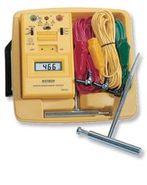
I recently got an Extech, 382152, Earth Ground Resistance
Tester Kit:
ExtechGroundTester.jpg

I put the spikes 20 feet and 40 feet away, connected
the electrodes, set it in the 20 ohm range, and got
1.6 ohms during a three minute test.

I realize this may be more of a personal interest than
a practical way to make money as an electrician.
The "Soares" book seems to be the name that keeps
coming up, so that is on my list of things to read in
the future. I would be interested in any other suggestions.
I am glad you asked, because I don't find a lot of local
electricians very interested in this. Thanks.
 
gar said:
080429-0623 EST

What was the configuration of the "ground electrode"?
Two rods with acorns, water service. The meter main
was in the backyard, which was where the ground rods
were, so took #4 copper to them first, and then under
the house to the front yard, which is where the water
service was. Of course, we were not
yet hooked to the utility.
I believe you implied that you you had a water supply line, I assume copper or iron from the street, bonded to two ground rods for your ground electrode.
How deep are the ground rods driven?
8 feet
How much space between the two rods?
About 10 feet
How far are the rods from the path of the water line?
On the other side of the house.
Roughly 25 feet.

What test equipment did you use to measure your ground rod resistance to earth?
Extech 382152 Earth Ground Resistance Tester.
(see post to Brian John) above.
What type of soil and moisture content?
Looked like Clay, and was not moist near the ground
rods.
Did you try measureing the resistance of just one of the ground rods bonded to nothing else?
I wish I had, but I only had a chance to perform
one test as we were tidying some things up before
the POCO put the meter on.
A long water line is going to provide the greatest surface area contact with the earth. Probably in virtually all cases far greater than one or two ground rods.
This makes sense, and it seems that was almost certainly
the case. Your questions are making me think
about this. I'm actually thinking of seeing if the water
pipe is leaking.

Thanks for your other comments as well.
 
gar said:
...I am well aware that using earth is as your safety ground is code violation and I simply try to provide quantitative data to support the reason why.

I think your misusing pronouns when you state "as your safety ground" because I will not use earth as an effective fault current path, the "safety ground" you speak of has nothing to do with fault current as you stated in you first sentence of Post #26.

Your data may be good for noise and such but even a zero resistance ground will not cause better operation of overcurrent protection devices, it doesn't make a safer system in this respect the electrodes only have to do what 250-4(A)(1) requires.

If noise is an issue it is best to install a supplemental grounding system but electrodes installed as per 250 part III will safely handle 250-4(A)(1)

gar said:
Whether a residence or commerical the same problems exist. Just variations, and also there are a number of people with rather sizable CNCs in their home shop.

Does the NEC specifically address CNC's, noise and controlling them?
 
JUST MY TAKE:

If you really want to have a understanding of grounding it is nice, to have an idea of how that stick we drive into the earth works or doesn't work (it just sits there 99.99999% of the time in relation to the electrical system. BUT and I mean a GIANT BUT, the real issue with grounding has NOTHING to do with electrodes (other than confusing the issue in most circumstances). Check out what a Equipment Grounding Conductor (EGC) is, and I meaneverything metallic that is bonded (connected together) in a structure, not just the conduit of copper/aluminum conductor we may install. This EGC is nothing more than a 4th conductor in a 240/120 (3-wire) VAC system and a 5th conductor in a 208/120 (4-wire) VAC system. This "extra" conductor has no mystical properties, performs no magic healing and is not enhanced by driving more electrodes into the earth.

90%, maybe 95% heck could be 99% of power quality issues I encounter are related to improperly installed distribution systems in particular intentional or accidental grounds on the neutral/grounded conductor downstream from the main neutral ground bond. Understanding how to test for this condition prior to energizing a distribution system, and how to locate and test for this condition after a distribution system is energized is (IMO) key to understanding how grounding works, in addition to the other CRITICAL features BONDING/grounding performs in a building.
 
080430-0722 EST

tryinghard:

To further clarify in the CNC area where people are doing stupid things.

If the Equipment Grounding Conductor (I like to call it "safety ground wire" to help the average person understand its purpose) is disconnected at the CNC and in its place a ground rod is substituted, then effectively the earth path back to the main panel becomes the EGC. This is totally unacceptable because of the almost certainly high resistance.

To serve the NEC safety requirement the EGC does not need to be zero, and their criteria is satisfactory. Also the NEC is not about communication noise, I agree.

I content that a directly connected RS232 system is a bad idea for the various reasons I have discussed here and on my web site. With electrical isolation in the RS232 path one can basically solve the ground path noise problem, and also the damaging voltage from a dead short from a hot wire to the EGC.

Even if the EGC is correctly installed to a CNC the addition of a supplemental ground rod at the machine only has a marginal effect on ground path noise. In other words it seldom solves the problem.

.
 
brian john said:
...90%, maybe 95% heck could be 99% of power quality issues I encounter are related to improperly installed distribution systems in particular intentional or accidental grounds on the neutral/grounded conductor downstream from the main neutral ground bond...

Ditto, me too
 
ONCE AGAIN THE EDIT CUT OFF TIME please extend for dolts like me........

I should add there are many cases where engineering dictates more than the NEC mandated grounding electrode systems. Mainly for lighting protection (I assume). I am not an engineer and while I do test these systems for compliance I cannot attest to the viability of these systems as being more efficient then the NEC mandated systems. This gets into an area of some disagreement, old habits and it worked in the past. There are firms that do nothing but sell enhanced electrodes, their engineers claim these systems are necessary and do work. I'd like to think an enhanced electrode provides some additional lighting protection to sites prone to lightning activity, but I have no engineering/scientific data this back this up.
 
080430-0909 EST

rexowner:

Your description of your ground system implies quite a bit of contact surface area, and on that basis a measurement in the range of 1 ohm in clay may be about correct. I doubt the ground rods contribute a great deal to the conductivity (reciprocal of resistance). Note the resistance of a group of shunt resistors is
R = 1/( (1/R1) + (1/R2) + (1/R3) etc )
When you parallel resistors you add the conductances. When you series resistors you add the resistances.

I will guess at 5 to 20 ohms for each rod alone.

A single ground rod is basically a monopole in a bulk material with some value of resistivity. If the current is not modified by other conductors there will be radial current flux lines radiating perpendicular to the rod. Since the circumference of a circle grows linearly with radius and we are dealing with a cyclinder this means the current density at any radius drops to 1/2 for a doubling of the radius. In addition as you increase the radius the resistance of a tubular section of fixed wall thickness (meaning radius 2 - radius 1 = a constant) resistance drops fairly rapidly. Thus, these factors cause the voltage gradient to diminish quite rapidly as you move away from the rod.

Actual tests are not run with this shape of field. You will have a field produced from two monopoles spaced some distance apart. However, using a standardized procedure you can get some meaningful results.

None of this has any effect on what happens inside a structure if nothing inside the structure connects to earth via some path that is not the service entrance earth ground array.

However, it is important for lightning or if you have a metal fence post in the backyard to which you connect an electrically hot wire. This hot wire in the backyard is where a GFCI becomes important because the earth resistance may not trip the supply breaker.

I have not used a Extech 382152, but I am familar with specifications for ground resistance measurement.

To a large extent ground electrode resistance to earth is not important except for lightning. However, when someone says "you need a good ground" with the assumption that ground is earth and they do not provide any quantitative data, then their statement is suspect and you need some ground rod resistance measurements.

.
 
Status
Not open for further replies.
Top