Current on GEC

Frank D

Member
Location
Los Angeles, CA
Occupation
Electrical project manager
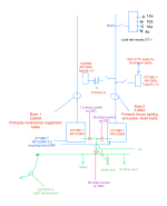
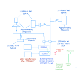
I posted this on the Grounding and bonding section, but I wanted to open it up to a wider discussion. We have a client with a facility that has two. 277/480v 3,000 services. Each Service is fed by a separate utility company transformer that supplies this building only.
Everything in the electrical system is original from the engineering. It’s a hotel with restaurants, a spa and other amenities large facility. The engineering is excellent and the distribution system remains intact and it does not apparently have any modifications or anything added.
We have measured 25 A of current on the GEC on one of the 3000 amp services. This service provides most of the single pole loads throughout the facility whether they are 277 or 120. The other service only has 1.5 A on the GEC is mostly two pole and three pole loads, which makes sense since all of the unbalanced currents usually come from single pole loads.
I was under the impression that the GEC should never have any significant current on it, yet with this large of a service, and it being a wye system, I can see where some current of the unbalance would flow in the ground conductor with that large of a load
 

Attachments

  • 4 S ground current  2.png
    4 S ground current 2.png
    240.6 KB · Views: 20
  • Distribution  2.png
    Distribution 2.png
    200.7 KB · Views: 20
In neither this thread nor the other did you tell us what the average load is on the services. A comparison to the neutral current would be most useful. This is important information. Without that info it’s impossible to say where the GEC current is totally unconcerning or indicates a potential issue. Personally I wouldn't be too concerned unless the ratio of Neutral/GEC current approached or exceeded the respective ampacity ratio. I mean these are 3000A services, so if you've got ~1000A of neutral current and only 2.5% flowing on the GEC I'm very unconcerned. With a good GES (you said impedance was 'as low as possible' on the other thread) it’d be entirely normal for current to flow via ground. Especially if there's a low impedance connection between the utility transformer neutral and the water pipe system, which you might not know. (For example if the transformer neutral is connected to a grounded secondary conductor that's also connected to another transformer's service that's also grounded to the water pipe network that might be continous metal, you'd have a low impedance parallel path.)

It could even be that some of the current on one of your service GECs is parallel neutral current for the other service.
 
As I commented on the other thread, your more than likely seeing some incorrectly wired circuits. Since the current is going from the electrode to primarily the house loads (lighting and such), I am still under the assumption that some of the 120V or 277V loads are incorrectly wired and are possibly using the EGC, building steel or cold water as a parallel path back to the neutral point of bonding. Whether that is the 120V circuit taking the long way home to the dry type or the 277V loads taking it back to the service. It wouldn't be too many considering the number of circuits you have in your system lol. I would start with recent work and amp clamp and isolate branch circuits or feeder circuits to identify. You could also try and amp clamp the GEC or EGCs to the dry types to see if that current is parallel to an existing route that is not the neutral.
 
BTW looking at your drawings again, I realized you marked 13kV.

Are you sure it is LADWP and 13kV? I don't think they have a 13kV distribution system. Is that possibly a customer owned transformer?
 
Do you have access to measure current on the 500 MCM cable at the bottom left of your first drawing. If there was a source of current there, then it could be distributed between all the other conducting paths connected to the GES, in inverse proportion to their relative impedances.
 
Do you have access to measure current on the 500 MCM cable at the bottom left of your first drawing. If there was a source of current there, then it could be distributed between all the other conducting paths connected to the GES, in inverse proportion to their relative impedances.

This is my thought as well.

Is the transformer neutral grounded? If it is, you would have a direct (and intentional) parallel path to the neutral. I would certainly _expect_ current flow on the EGC in that case.
 
As I commented on the other thread, you’re more than likely seeing some incorrectly wired circuits. Since the current is going from the electrode to primarily the house loads (lighting and such), I am still under the assumption that some of the 120V or 277V loads are incorrectly wired and are possibly using the EGC, building steel or cold water as a parallel path back to the neutral point of bonding. Whether that is the 120V circuit taking the long way home to the dry type or the 277V loads taking it back to the service. It wouldn't be too many considering the number of circuits you have in your system lol. I would start with recent work and amp clamp and isolate branch circuits or feeder circuits to identify. You could also try and amp clamp the GEC or EGCs to the dry types to see if that current is parallel to an existing route that is not the neutral.
The running load we do not have. With the buss duct system there is no safe way to measure the total load current.
Do you know of any engineering, or other standards that would specify an acceptable % range of GEC current?
I agree with the level of current not being that bad considering the size of the service. Another interesting point is that, the second service that has mainly two pole and three pole loads on it has a very small ground current, and the service with the larger current on the GEC has most of the single pole loads on the site which is where the unbalance typically originate. They seem proportionate.
 
In my experience, there is no real ratio of acceptable measured current on the GEC. There are, however, reasons why it can exist without creating issue or harm. That is why the code concerns itself with "objectionable" current. Sometimes you can get inductive currents on grounded conductors where run with loaded circuits. That is kinda what it looks like on the 2nd maintenance service. You can't do anything about that. But the first service could have something incorrectly wired. Or not.

In this scenario, you need to investigate why you have current on the GEC. As Winnie and Synchro pointed out, it could be an acceptable result of the grounding and bonding of the 13.8kv transformer. I should mention, that I still do not believe that is LADWPs transformer. I think that is customer owned. I spoke with a buddy of mine that works at LADWP and he confirmed they don't use a 13.8kV. Maybe it is Pasadena or somewhere else though. Knowing this would also help. We are going to want to know if the transformer is owned by the utility or owned by the customer. It changes the way we might evaluate where the currents are coming from.

Regardless, that grounded SSBJ or GEC, or whatever you want to label the 500MCM from the transformer to the services could be serving as a parallel path back to the transformer for normally occurring neutral currents. This wouldn't be much of an issue.

You will need to figure out a way to diagnose it. Whether that is scheduling maintenance outages or putting in power monitor CTs on all 5 conductors at each bus tap location. phase, phase, phase, neutral, egc.

And then the same on each dry type on the low side of the dry type. phase, phase, phase, neutral, SBJ or GEC at the transformer.

I would start with panelboards that feed lighting loads and then work your way back to the service.

Lastly, new electric water heaters? New electric ranges? New electric LED lighting? Any recent work to water or electric?

You have a hotel, restaurant, and spa. I would start looking for renovations that could have created the issue.
 
The running load we do not have. With the buss duct system there is no safe way to measure the total load current.
You could look at the demand from the utility.
Do you know of any engineering, or other standards that would specify an acceptable % range of GEC current?
While it does not specify a % the IEEE Green book is worth a read.

Your diagram is nice but does not show any ATS's. No backup power? I only mention that because I have found a accidental N-G bond in a ATS before.
 
At a large facility here (not one I work on) I have herd they keep having a problem with "tin whiskers", apparently the basement of the building is damp enough that thin strands of tin grow from tin plated AL bus bars over time, first its like a capacitor causing a small current leakage, but can develop into a short if not detected early, I dont know much about it but you might look into it. I herd it only occurs on 480V and up so probably not your 208 sections, others here will know more than me.
 
Top