current returning to a different source

Status
Not open for further replies.
Rick Christopherson said:
Umm, Didn't you realize that the current flow in both of your pictures was in the same direction?

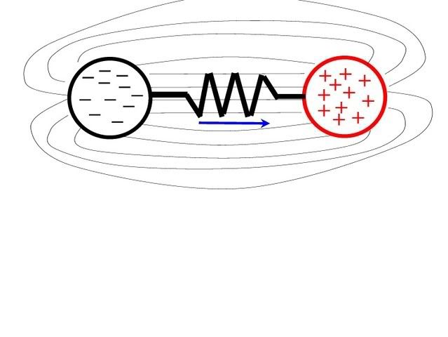
Of course. The purpose was to show that either drawing could be used to represent a single resistor connected to a single voltage source.

Rick Christopherson said:
These pictures do not represent a closed path (aka circuit) but two parallel paths from one potential to another.

Parallel paths? Please describe the parallel path in the third diagram. There is only ONE resistor and there is only ONE source.
 
crossman said:
In post 246 you quoted and bolded this statement which I posted earlier.

"A single conductor between these two charges is a completed circuit."
I have not contradicted myself. I was quoting you, and as I already stated in a previous message when you tried to pull this garbage with semantics:
Rick Christopherson said:
I did not correct you on your misuse of the term "circuit" in the above quote because I felt that would be as pedantic as correcting someone's spelling errors. I knew what you were saying regardless whether you correctly called it a network or a circuit.
You said One Wire. If you are going to quibble over whether I should have corrected you or not, then show me where the return path is between the two bodies that would constitute a circuit.
 
crossman said:
Of course. The purpose was to show that either drawing could be used to represent a single resistor connected to a single voltage source.
Oh Bull! This is the Engineering forum. Do you honestly expect me to believe that you were trying to explain to someone, that you know is an electrical engineer, that a circuit path is the same regardless whether it is a straight wire or a curved wire? Did you really think that this might be some sort of shocking revelation to an engineer?:mad:

You were talking about those diagrams as though they somehow revealed that a circuit exists, which by definition includes the return path.
Crossman said:
A little redrawing will illustrate that this is indeed a complete circuit from one side of a voltage source to another.
 
Rick Christopherson said:
Oh Bull! This is the Engineering forum. Do you honestly expect me to believe that you were trying to explain to someone, that you know is an electrical engineer, that a circuit path is the same regardless whether it is a straight wire or a curved wire? Did you really think that this might be some sort of shocking revelation to an engineer?:mad:

Rick, at this point, YES. Your previous statements on this thread, especially today, and your reluctance to offer any explanations have shown a serious lack of understanding of the concepts at hand. I have no evidence whether you are, or are not, an engineer.

Man I am serious. I am sincerely trying to explain to you what you apparently are not seeing. You can get mad and you can exclaim "Oh Bull" and you can make bogus assumptions about the intent of my latest diagrams if you want. But I absolutely positively felt I needed to break this down to the most simple elementary terms to show you that a complete circuit exists.

Rick Christopherson said:
You were talking about those diagrams as though they somehow revealed that a circuit exists, which by definition includes the return path.

A circuit does exist. Look very carefully at the third diagram. From the body on the left which is the negative terminal of the voltage source, a wire extends to the resistor. From the resistor, another wire "returns" to the other side of the source at the positive body. As for a complete circuit, this is no different than a "hot" wire leaving a breaker going to a light bulb and a neutral wire from the bulb back to the neutral bar. If you want to leave out the resistor and just short from positive to negative with a single wire, it is still a completed circuit.

The simplest functional circuit has a voltage source and a load connected in a complete path. The third diagram is exactly that. And so is the second diagram.

I see no further point of discussing the issue unless you can come up with something scientifically valid which can show that the second or third diagram is not a complete circuit.

Thanks again for starting an interesting line of discussion.:smile:
 
Last edited:
show me where the return path is between the two bodies that would constitute a circuit.

Rick, one final comment: The negative body, the positive body, and the electrostatic field between them constitute a voltage source. There is no need for a "return wire" between the bodies.

Ignore the bodies and just place a black box over the bodies. There is a wire coming out of the left side and a wire coming out of the right side. Connect these two wires together. Current flows. It follows that there is a voltage source in the black box.
 
Last edited:
crossman said:
There is no need for a "return wire" between the bodies.
This is the very point I was making way back at the beginning of this discussion when I took so much heat about it. Rattus even stated that this was heresy. Go back and reread this entire thread from my original posting. 90% of the responses in this entire thread were arguing that a return path must exist before current will flow. Several postings specifically stated that even if you had a conductor connected across a difference in voltage, no current could flow until you closed the path. The electrons needed to flow in a circular path.

All of these arguments about capacitance were based on the perceived need to close the return path between two different voltages. No current could flow unless we somehow tied it back into the grounding system (to paraphrase several postings by several members).
======================================

To your credit, I see that your first couple of postings supported the same conclusion that you just stated this morning, but in between the beginning and the end, you too got sidetracked on this need for a return path.

I don't want to mistakenly put words in your mouth, but if I am reading your postings from today correctly, you and I are in agreement with this information (with a couple of minor intermediate digressions).

If you and everyone else is finally in agreement that current will flow through a single conductor from one voltage to another voltage, then I am ready to explain why this situation exists.
 
crossman said:
A drawing of what you feel the electrostatic field should look like would be appreciated.
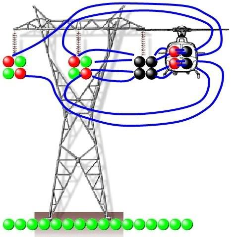
Force lines regarding all three power lines (my best guestimate)...

Line A is full negative while B and C are at half positive.

View attachment 1251

Now let's put that in the tower scenario...

View attachment 1252

Non-connecting lines at the periphery of the force "rectangle" will typically extend out and around to an opposing field.

Another note is: while there may be potential differnces between the power line and ground or grounded parts such as the tower. Ground and grounded parts have no electron imbalance and therefore do not an generate an e-field, attracting or repelling. Your earlier statement about the ground having an equal and opposite e-field is unfounded. The 3? power lines are the only bodies generating an e-field. Therefore my comparison of e-field strength at the helicopter vs. ground stands.

To go any further we must go back to basics. The following image depicts three atoms of a substantially conductive element (Cu if you like).
  • Red is positive by one electron charge.
  • Black is negative by one electron charge.
  • Green is atomically neutral.

View attachment 1253

Now draw the e-field force line...

View attachment 1254

That was quite easy... eh?

Note that pretty much wherever you place the neutral atom, the force line will always go from the positive to the negative atom.

So, you probably ask how this applies to the situation under discussion...

I leave drawing the e-field force lines as an excercise for the reader!

View attachment 1255
 
mull982 said:
What happens when current originating from from one source (transformer) returns on a nuetral to a different source (different transformer)?

Say I have a 120V single phase transformer 1 which is sending current out via the hot leg of transformer 1 to a device, however the the nuetral coming off of the device does not return to the nuetral of transformer 1, but rather the nuetral of a different transformer I'll call transformer 2. Will the load or device still see the correct current and voltage it needs or will no current circulate because there is no path back to its origonal source?
It all goes back to the generating plant,
 
Rick Christopherson said:
I don't want to mistakenly put words in your mouth, but if I am reading your postings from today correctly, you and I are in agreement with this information (with a couple of minor intermediate digressions).

Rick: Thank you for this post. About an hour ago, I was just sitting around trying to relax, and a similar conclusion popped into my head. Earlier, it seemed we were at each other's throats, but the light bulb blinked on and it occurred to me we aren't so far apart after all.

Here are my thoughts (I am makng assumptions about what you were thinking as compared to what I was thinking. Correct me if I am wrong). It seems our issues are with the definitions of terms, not with what is actually happening in the real world.

It dawned on me that your definition of "return wire" is different than my definition of "return" wire. With me being an electrician, I'll use a typical 120 volt dwelling circuit as an example: In most instances, to me, a "return wire" is a wire that goes from a switch to a light fixture. It completes the path from the hot wire/switch to the light fixture. But another use of "return" could be the neutral of a circuit. In other words, to me, a "return wire" is a wire that carries the current from either a switch to a load, or from a load back to the neutral (one side of the source). For verification, please see my post # 264, my third paragraph, to see my usage of "return wire".

I now realize (my assumption) that your definition of "return wire" was a wire running from one side of a source to the other side of the source (for example, from one charged body to the other) and would be used to allow the electrons to go back to the other side of the source once they had traveled through the "load conductor". Am I correct in this?

So (again my assumption) you were thinking that I was saying that, along with the current carrying wire from one body to the other, there had to be another "return" wire between the bodies? I believe this is what you thought I said based on your responses to my diagrams of today.

Now, if I am correct that this was your definition of "return wire," and comparing to my definition of "return wire," then I can totally understand why you were so frustrated earlier. Believe me, I was frustrated!:smile:

We may also have some varying definitions of "complete circuit" and "voltage source" but I feel we can resolve these. I have some more diagrams in my mind that I will post tomorrow afternoon. I will be very careful to insure that you and I understand the terms I use. I think they will clear up that we are actually a lot closer in our thinking than we originally thought. I would do the diagrams tonight, but I am on slow-speed dial-up and I just don't have the energy right now anyway!;)

Edit: correct typo
 
Last edited:
Smart $ said:
Force lines regarding all three power lines (my best guestimate)...

Smart$, your diagrams are beautifully crafted and instructional. Your comments about no electrostatic field to ground have me thinking.


Smart $ said:
Another note is: while there may be potential differnces between the power line and ground or grounded parts such as the tower. Ground and grounded parts have no electron imbalance and therefore do not an generate an e-field, attracting or repelling.

To a certain degree this makes sense, but I have reservations.

1) I think up high around the wires, the electrons in the tower cannot help being pushed/pulled around by the electrostatic fields. Electrons in the tower will be attacted to the positive wires, leaving positive charges near the negative wire. I do not believe that the tower being grounded has anything to do with it.

2) If this is a grounded system, the earth is connected into the voltage source. The earth is essnetially another capacitor plate and will have an electrostatic field which extends upward and mingles with the fields from the three phases.

3) The earth cannot be assumed to be electrically neutral. Charges can accumulate and move around based on other charges in the vicinity. For example, lightning.

^^all 3 my humble opinion^^


Smart $ said:
Your earlier statement about the ground having an equal and opposite e-field is unfounded. The 3? power lines are the only bodies generating an e-field. Therefore my comparison of e-field strength at the helicopter vs. ground stands.

From your diagram, I will concede that the electrostatic field from earth may not be as strong as I thought. But I still feel it exists.

Now, as for the helicopter: If you fly a chopper into the electrostatic field on the right-hand side of the negative wire, look where the lines go. Electrons will be pushed/pulled to the right-hand side of the chopper leaving the left-hand side positive. This can be represented by a capacitor from the positive wires to the helicopter and another capacitor from helicopter to the negative wire. There also needs to be a variable resistor in parallel around the helicopter to negative wire capacitor.

If you notice, this is the same circuit as drawn previously except the helicopter-ground cap is replaced by a helicopter-positive wire cap. Essentially the current flow operates the same except replace "my earth" with your "positive powerlines".

To go any further we must go back to basics. The following image depicts three atoms of a substantially conductive element (Cu if you like).
  • Red is positive by one electron charge.
  • Black is negative by one electron charge.
  • Green is atomically neutral.
Good point, but if we had three negative ions near a neutral atom, the electrostatic field would extend to the neutral atom.

Thanks again for the daigram and thoughts. This is good stuff and deserves some more input to further refine the situation.
 
Smart $ said:
Another note is: while there may be potential differnces between the power line and ground or grounded parts such as the tower. Ground and grounded parts have no electron imbalance and therefore do not an generate an e-field, attracting or repelling.

Need to add another thought. While I agree thatthe tower does not gain any electrons and remains neutral overall, there will be isolated regions where charge imbalances occur. If a negatively charged body is brought near the right-hand side of the tower, some of the electrons in that portion of the tower will be repelled away from the charge.

By the same mechanism, the negative wire pushes electrons in the tower away from it. The positive wires pull the electrons in the tower towards them. Charge imbalances do occur in the tower, just like they occur in the helicopter when it approaches the negative wire.
 
crossman said:
It dawned on me that your definition of "return wire" is different than my definition of "return" wire.
No. When it comes to standard electrical systems, what you call a return line is the same as myself and anyone else considers a return line.
crossman said:
I now realize (my assumption) that your definition of "return wire" was a wire running from one side of a source to the other side of the source ..... Am I correct in this [assumption]?
Unfortunately, I mistakenly lead you to draw this conclusion regarding what I considered a return, and that is a mistake on my part. That was because I automatically jumped a few steps ahead and applied your picture of an electric dipole into the helicopter situation. I shouldn't have done that yet, but it is the next step.
crossman said:
We may also have some varying definitions of "complete circuit" and "voltage source" but I feel we can resolve these.
Yes, and this is in part why I ended up misleading you about the comments above (and I hope that doesn't come back to haunt me later). What you drew in post #254 on page 26 was not a voltage source, as you kept calling it; It is an electric dipole. If it was a voltage source, then you would in fact need some type of mechanism to return the electrons back into the circuit, such as an electron pump. (I don't recall if I specifically called this a return line, or if I just implied that. In any event, this would not be called a return line. There is a reason why I may have made this faux pas, and that should be clear later.)

I am going to stop here and pick this up in a new posting, where I can start fresh and explain this better.
 
crossman said:
Need to add another thought. While I agree thatthe tower does not gain any electrons and remains neutral overall, there will be isolated regions where charge imbalances occur. If a negatively charged body is brought near the right-hand side of the tower, some of the electrons in that portion of the tower will be repelled away from the charge.

By the same mechanism, the negative wire pushes electrons in the tower away from it. The positive wires pull the electrons in the tower towards them. Charge imbalances do occur in the tower, just like they occur in the helicopter when it approaches the negative wire.
I concur with your assessment, yet I'd like to add one point. The distribution of charges in the tower are the result of an e-field passing through the structure. In other words, and more to the point, a resultant not a causal effect—same as with the helicopter. The effect creates no new or additional e-fields (though it may warp force lines, compared to those when the tower is not present).

Edited to elaborate ()
 
Last edited:
crossman said:
Smart$, your diagrams are beautifully crafted and instructional. Your comments about no electrostatic field to ground have me thinking.


To a certain degree this makes sense, but I have reservations.

1) I think up high around the wires, the electrons in the tower cannot help being pushed/pulled around by the electrostatic fields. Electrons in the tower will be attacted to the positive wires, leaving positive charges near the negative wire. I do not believe that the tower being grounded has anything to do with it.

2) If this is a grounded system, the earth is connected into the voltage source. The earth is essnetially another capacitor plate and will have an electrostatic field which extends upward and mingles with the fields from the three phases.

3) The earth cannot be assumed to be electrically neutral. Charges can accumulate and move around based on other charges in the vicinity. For example, lightning.

^^all 3 my humble opinion^^
My view to all three is as I noted in another post?these are all resultant, not causal effects, and create no new or additional e-fields other than those generated by the power lines.

From your diagram, I will concede that the electrostatic field from earth may not be as strong as I thought. But I still feel it exists.

Now, as for the helicopter: If you fly a chopper into the electrostatic field on the right-hand side of the negative wire, look where the lines go. Electrons will be pushed/pulled to the right-hand side of the chopper leaving the left-hand side positive. This can be represented by a capacitor from the positive wires to the helicopter and another capacitor from helicopter to the negative wire. There also needs to be a variable resistor in parallel around the helicopter to negative wire capacitor.

If you notice, this is the same circuit as drawn previously except the helicopter-ground cap is replaced by a helicopter-positive wire cap. Essentially the current flow operates the same except replace "my earth" with your "positive powerlines".
For the sake of discussion I'm going to go with your concept of capacitance/capacitors...

Refer to my elemental diagram of the tower-helicopter scenario, the one with 4 atoms each for power lines and helicopter. When the arc occurs, two electrons jump the air gap and thereby 4 atoms are neutralized, atomically speaking: two in the power line and two in the helicopter. This effect is attributable to basic physics and not the result of capacitance.

Sure your model of a capacitor shorted by a variable resistor essentially produces the same result... but why are we even talking about electrical circuit components when the effect is much more elemental? Could it simply be that as electricians we must explain anything electrical in nature by way of a circuit description? I believe that is mostly the case here in this discussion! :grin:

Good point, but if we had three negative ions near a neutral atom, the electrostatic field would extend to the neutral atom.
I agree... but what would be the result if the negative ions where such by one electron charge each? (ummm... let's make this question rhetorical, so as to not get off topic.)

Thanks again for the daigram and thoughts. This is good stuff and deserves some more input to further refine the situation.
Your welcome.
 
OK, Starting with a fresh posting, what Crossman drew previously is very close to what is happening with the helicopter (and I'll steal your drawing).

Oh, One preface: Please don't hold it against me if I screw up the polarity differences between the direction of current flow and charge flow. I have a hard enough time keeping this straight in simple situations, and it really is not important which direction is which for this application. OK?

bodies2.jpg


What Crossman drew is an electric dipole--one positive point source, and one negative point source. Even though the near-infinite-length power wire doesn't fit the model of a dipole, for a 2-dimensional representation, it is close enough for this discussion. The Earth and the power pole are actually negligible, and you will see the reason in a moment (i.e. more than 12 feet).

One body represents the power line and the other body represents the helicopter. The resistor between the two bodies actually represents the ionized air between the line and the probe.

Ironically, this whole concept was just described on the History channel just one hour ago. Even though this was a repeat episode, the one piece of information I picked up this time around that I hadn't specifically noted before was that the area of influence from a 500kV line is 12 feet, so I will use their number as a reference (This is part of the math that I said 28 pages ago that I didn't want to calculate myself).

When the helicopter is outside of this 12 foot radius, it will have some neutral voltage. (We don't know this voltage, nor do we care, because we are going to charge this anyway.)

When the helicopter gets within this 12 foot radius, the technician extends the probe to ensure that the metallic probe is the closest conductor to the line. Up to this point, there is no charge transfer between the line and the helicopter, but the helicopter is becoming immersed in the electric field of the line. Without a charge transfer, the helicopter (as a whole) has not changed its voltage with respect to the line. There will be some changes in charge distribution across the components of the helicopter because some components are more deeply immersed in the electric field than others, but this is really not terribly applicable to the overall concept yet.

When the probe gets within a foot or two of the line, the voltage difference between the helicopter and the power line exceeds the dielectric breakdown voltage of air for the specific distance (I believe this is 20,320 volts per inch at STP, so the initial breakdown for 500kV should be about 2 feet.) At this point, we now have a high-resistance current-path/current-transfer between the line and the helicopter.

As I stated in the original supposition, the helicopter hovers within this band of breakdown without fully contacting the line. I personally don't know the conductivity of air under these conditions (ionization, temp, etc), but if we (anyone out there) knew this, we could use Ohm's Law to tell us how much current was flowing, based on the voltage difference between the line and helicopter, and the distance.

So for the positive half-cycle of the power line, the line will be delivering current to (pulling charge from) the helicopter in an effort to equalize the voltage between the two. Because this is occurring via a high-resistance conductor (air) the charge transfer will be slowed down (similar to an RC charge time). (Edited to fix the current/charge polarity here.)

Since the charge transfer is happening slow, due to the RC time, we can't ever fully charge the helicopter to equal the potential of the power line. But just as we are getting close to bringing the helicopter up to the 500kV charge, our buddy, George Westinghouse, does a flip-flop, and the power line goes into its negative half-cycle. Now we have a helicopter with a positive voltage, and a power line with a negative voltage. So the charge transfer reverses, and we start dumping charge back into the helicopter in order to reduce the voltage of the helicopter relative to the line.

Because this is occurring with an extremely high voltage, with a high resistance path, we can never keep up with the charge transfer, and can never equalize the potential difference between the two bodies. As a result, the conductor between the helicopter and the line (this is both the air and probe, by the way) will have an AC current flowing.

Yes, there will be some stray capacitance between the body of the helicopter and the Earth (and other sources), but this is not what is driving the charge transfer, and more importantly, this is not resulting in a (significant) return path back to the power substation. It is this last statement that is the premise behind my entire point.

Electrons do not have sir-names or home addresses. :smile: They don't care if they ever return home or not. All they care about is that they move from a negative voltage to a positive voltage. They don't care whether the positive voltage comes from one source and the negative voltage is from a different source. They are simply lazy, and want to move to the lowest potential, regardless where that is.

With a fresh mind this morning, I went through and cleaned up the polarity mistakes regarding which direction current flows as opposed to which direction electrons travel. For those of you following this discussion that didn't know there was a difference, here is the reason:

Electrons, being a negative charge, want to move from a negative voltage to a positive voltage. However, in the early days of electricity, electrical current was defined as the movement of "positive charge" (I could be wrong, but I think Ben Franklin made this assumption). As a result, when we talk about electrical current, it flows from positive to negative. This became standard convention before we realized that it was negative charge that was moving, not positive charge. So when we talk about electrical current, it is flowing backward from the actual direction of the electron travel. Normally this isn't much of an issue, until you start mixing terminology, which is when I screw it up all the time.

I think I fixed all of the original polarity mistakes, but I left the preface in at the top just in case I missed one.
:-?
 
Last edited:
Rick Christopherson said:
Electrons do not have sir-names or home addresses. They are simply lazy, and want to move to the lowest potential, regardless where that is.

And the problem arises when we misunderstand just exactly where that lowest potential is.

Concerning the helicopter and looking at Smart$ diagram. I still believe that we cannot omit the effect of the positive powerlines on the helicopter.

I still think there are some electrostatic lines which involve the earth. This is beside the point though. The total electrostatic field affects the helicopter regardless of whether it is only from the powerlines or from the powerline and earth.

elementaltowernhelicopter1.jpg
 
Somebody please give me a definition of "voltage source".

Definition of "complete circuit"?

Definition of "return wire"?

Thanks in advance!:smile:
 
Last edited:
Enuf Awreddy!

Enuf Awreddy!

I prefer to think of a lone charged capacitor as a transient voltage source. To discharge this cap, one would connect the leads through a wire, resistor, or whatever. Certainly, one would draw the schematic that way, and if you simulated it, you would do essentially the same thing. Then, as the cap discharges, electrons RETURN to the opposite lead just as they would with a battery or generator for a source.

Now, it really doesn't matter because this scenario has nothing to do with the OP's original question. Neither does it support the helicopter example.

Now, Smart is claiming there is no capacitance between the energized line and earth which I do not believe, but even if he is right, it doesn't matter because the helicopter is interrupting the field between two energized lines. The result is still two caps in series, and certainly we will see line to line currents through these caps. Then as the arc is struck, we have a lo-Z path and then a short between the line and the copter. The result is big lump on that line with a resultant increase in line to line current.
 
Rick Christopherson said:
There will be some changes in charge distribution across the components of the helicopter because some components are more deeply immersed in the electric field than others, but this is really not terribly applicable to the overall concept yet.

To me, the electrostatic field IS terribly applicable to the overall concept of the helicopter. IMHO it is the major factor.

Rick Christopherson said:
Yes, there will be some stray capacitance between the body of the helicopter and the Earth (and other sources), but this is not what is driving the charge transfer, and more importantly, this is not resulting in a (significant) return path back to the power substation. It is this last statement that is the premise behind my entire point.

I am still not convinced that something other than capacitance is the major factor.

Rick Christopherson said:
Electrons do not have sir-names or home addresses. :smile: They don't care if they ever return home or not. All they care about is that they move from a negative voltage to a positive voltage. They don't care whether the positive voltage comes from one source and the negative voltage is from a different source. They are simply lazy, and want to move to the lowest potential, regardless where that is.

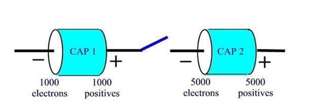
Rick, look at the following: We have two identical capacitors but each capacitor has been charged to a different voltage level. Cap 1 has 1000 electrons on the left plate and 1000 positive charges on the right plate. Cap 2 has 5000 electrons on the left plate and 5000 positives on the right plate.

If the switch is closed, what happens?

capcap.jpg
 
rattus said:
...

Now, Smart is claiming there is no capacitance between the energized line and earth...
Nonsense. I have not said there is no capacitance between the power lines and earth. I believe capacitance exists between any two bodies of mass, all the way down to the atomic, perhaps sub-atomic level. So should we include the effects of capacitance in all our electrical discussions? I think not. When in cases where specific capacitance effects contribute nothing to the situation, they can rightfully be ignored. I claim, in this case, the effect of capacitance between the power lines and earth are negligible.
 
Status
Not open for further replies.
Top