Floating Neutral

Merry Christmas
Status
Not open for further replies.
realolman said:
It took me a while to get this post accomplished... crossman, I don't understand your second hypothesis. Why would one phase be subtantially higher than the other with respect to the neutral bar.


service.jpg


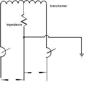
The connected lods acting as voltage dividers would do that according to their impedances, but I dont see the high impedance (bad / no connection ) of the neutral doing it.
Normally, the impedance to neutral shown in your diagram is very low compared to the load impedance. The loads in this case are not a voltage divider; the same current does not go through each load. Each load is across 1/2 of the secondary winding.

If the neutral is open (impedance very high), then the loads will act as a voltage divider because the same current goes through both loads. A heavy load (low impedance) on one leg will have a low voltage drop and a light load (high impedance) on the other leg will have a high voltage drop from the same current going through both loads.
 
Here is another illustration from Ed MacLarren.

3wire3.gif


Roger
 
Roger that diagram says it all and hopefully will open eyes. Only wished there was a third drawing showing the open neutral with say a 25-ohm ground at the service drop, and say a 5-ohm ground at the Xo of the service transformer to show how crazy it gets and impress why earth cannot be used a conductor for low voltage aka NEC applications.
 
dereckbc said:
Roger that diagram says it all and hopefully will open eyes. Only wished there was a third drawing showing the open neutral with say a 25-ohm ground at the service drop, and say a 5-ohm ground at the Xo of the service transformer to show how crazy it gets and impress why earth cannot be used a conductor for low voltage aka NEC applications.

Good morning Dereck, hopefully one of the members can put together an illustration showing it, I am not that good at it. :smile:

I wish Ed were still active.


Roger
 
dereckbc said:
Roger I can do it, just don't have the time or inclination to do so. :smile:

Well, the truth be known, that's kinda where I'm at.:grin:

When I do start something like that I'll spend hours at it and weekends don't seem to have enough hours anyways.

Roger
 
72.5kv said:

72.5, you will have to upload your image to a web site to be able to post it in this manner.

But with that said, we are not talking MV, HV, or an SWER, we are talking about LV (600v and below) wiring.

Roger
 
roger said:
But with that said, we are not talking MV, HV, or an SWER, we are talking about LV (600v and below) wiring.

I agree, what works above a few 1000 volts is not what works below 600 volts.
 
Water main ground

Water main ground

roger said:
Sparkygriffin, the grounding system to the earth by itself would not have anything to do with saving the houses equipment. Electricity (current) does not seek earth, it seeks it's source and for sake of conversation, we will say that the source is the transformer on the pole.

No matter how good the houses ground system is, if the transformers ground does not have a measurable resistance back to the houses ground, there will be damage.

The earth would only be a conductor, it would not be the end of the circuit.

The 4.8 amps comes into play in Ohms law.

If we have a grounding system that meets the 25 ohm number (between the House and the Pole Ground wire) we could use ohms law to calculate how good of a conductor we have in E / R = I or 120 / 25 = 4.8 amps, this would be all the conductor (earth) could handle before failure.

Roger
You keep refering to this scenario where the ground is not capable of carrying the neutral current.
I am on long island and the most common by far is a water main or well point ground suplemented by a driven ground rod. Until recently most say 90% of water mains are copper and with the offsets I am willins to go out on a limb and estimate the average distance of a water main is 50 feet.
All of these mains are tied together to the street main. Lets say an average 30 kv xformer serves 5 or 6 houses that is 5 or 6 neutral taps to the individual houses.
Where the neutral fails is critical because if it is closer to the xformer more houses will be affected. If one house looses its neutral connection at the top of the service drop And it has a water main connection it will send current through ALL of the service neutrals and All of the water mains connected And also through the poor ground connections And the Xformer down ground radiating from ALL of the houses connected.
When you put the symbol for infinity at the number of paralell paths into the equation you end up with a pretty low resistance. When the neutral is lost right at the xformer Please just call the fire department.
When investigating where the neutral is broken you must take all paths into consideration. These low numbers will only float when only ground rods are used it is Not the norm in my specific area.
 
Quo, read my posts #17 and #25, you will see where I addressed your scenario more than once.

Current flowing on metallic water systems is not the same as current flowing through earth.

Below is another illustration from Ed MacLarren that will help you see how a metallic water system would work, but it would also be a dangerous situation.


Neutral2.gif


Roger
 
quogueelectric said:
I am on long island and the most common by far is a water main or well point ground suplemented by a driven ground rod. Until recently most say 90% of water mains are copper and with the offsets I am willins to go out on a limb and estimate the average distance of a water main is 50 feet.
Your situation is unique, and as Roger said current flowing through water pipes is not current flowing through the earth. The same principle can be applied to your CATV lead in wire, and in fact has happened resulting in fires when the nuetral is lost.

A lot of new construction today uses PVC water pipe to the water meter. And many water utilities install dielectric fitings at the water meters to prevent current from flowing as they have had many personnel injured while removing water meters.

All I am saying is what works in your neighborhood cannot be applied everywhere.
 
Yes I am aware of dielectric fittings

Yes I am aware of dielectric fittings

dereckbc said:
Your situation is unique, and as Roger said current flowing through water pipes is not current flowing through the earth. The same principle can be applied to your CATV lead in wire, and in fact has happened resulting in fires when the nuetral is lost.

A lot of new construction today uses PVC water pipe to the water meter. And many water utilities install dielectric fitings at the water meters to prevent current from flowing as they have had many personnel injured while removing water meters.

All I am saying is what works in your neighborhood cannot be applied everywhere.
We are required to put jumpers across the meters for electrical continuity and so they may be safely serviced when they are installed on metalic systems and inside the house.
This example is not just my neighborhood it is all of long Island which comprises 4 large countys. The water pipes are in very large surface area in contact with the earth. Ohms law would assure that current would be flowing as all parralel paths are used to get back to the source. As I said when the number of parallel paths aproaches infinity the resitance aproaches zero.
The other houses on the xformer are still tied into the utility neutrals returning the current back to the source which is the utility transformer.
I am also aware that on longer distances and newer instalations everyone is changing to plastic as the copper prices rise. This will make the neutral termination even more critical in the future.
 
I have re read the posts

I have re read the posts

roger said:
Quo, read my posts #17 and #25, you will see where I addressed your scenario more than once.

Current flowing on metallic water systems is not the same as current flowing through earth.

Below is another illustration from Ed MacLarren that will help you see how a metallic water system would work, but it would also be a dangerous situation.


Neutral2.gif


Roger
And agree with them The point I was trying to make is that in my many years of experience I seldomly have to rely on ground rods alone as the sole means of grounding in this area.
 
quogueelectric said:
And agree with them The point I was trying to make is that in my many years of experience I seldomly have to rely on ground rods alone as the sole means of grounding in this area.

Nor should you rely on rods as sole means - it sounds as if (like my area) that metallic watter mains are required (by plumbing codes), and if there is one, by electrical code you are required to use it, and incorporate it into the electrode system. Since water mains require full sized conductors and to be supplemented with rods, as well as being bonded across dielectric (Which is not required everywhere, and since often done by plumbers - not paid attention to - if even allowed....) - I see that as safer electrically speaking - while not safe for plumbers if there is a problem. Or for that matter an electrician working in a home nearby an unknown fault condition, as current would be going through the bonding jumpers to the neutral in another home or building. That spark would be an eye opener....
 
we are not getting

we are not getting

That ohms law provides for current traveling from the water main surface copper through the EARTH to the SOURCE.
 
Neutral

Neutral

The home?s ground rod connection from the neutral to earth only serves two purposes:

1. Lightning path to earth: Since lightning is a source voltage potential to earth, the ground rod provides a current path to earth (ground). Therefore lightning strikes either to the house or to the power line (or vicinity and induced) will return to earth via the rod. It is not going to divert/drain all the potential, but it does offer a ?level? of protection.

2. Minimizes voltage gradient: When the neutral is lost and voltage division occurs on phase to neutral (120 VAC) loads, the neutral bus voltage of the house shifts to the level relative to the load voltage imbalance. For example, if the phase to neutral voltage division is 200 VAC and 40 VAC, the voltage measured from the house?s open neutral to the transformer?s midpoint (240 VAC xfmr center tap) would be 80 VAC. The house?s ground rod connection to earth does not hold the neutral bus to 0 volts. However, the safety benefit is that the person touching neutral voltage is at the same potential (and so are the water pipes since they too are connected to the neutral and earth at the house).

Note that even if the earth ground at the transformer pole and the earth ground at the house are very good (low resistance), the current path of the conductors of the imbalanced neutral loads required to maintain 120 VAC would be the phase conductors and earth. The separation of these conductors creates a high impedance path, which is still too high to eliminate the voltage division.
 
Status
Not open for further replies.
Top