Ground rod resistance

Status
Not open for further replies.
While groud testing a gravel plant where the soil is high concentration of lava rock, the ground rods will not read a resistance of less than 50 ohms. (25 ohms is max resistance) An extra rod has been driven where the grounding electrode conductor at the main disconnect ties to the two rods that are 6 feet apart.

From the main distribution board, there are other subpanels. The conduit feeding each of the subpanels has a bonding conductor that is terminated in the normal mechanical bonding fashion. The the electrical subpanels are mounted on their own support system. All of the conveyors, crushers, subpanels, generation equipment, & etc. are mechanically bonded via a bonding conductor and ground rod system. There are a total of 5 rods and they are tied together, and to the mechanical equipment. These, also, tie back to the main grounding system.

MSHAW is the jurisdiction for this installation. Our company is required to supply a report verifying that the grounding system meets the requirements of 25 ohms resistance. Does the code section, 250-56, indicate that all that can be done has been done by adding the extra rod? And, when I log that there are 50 ohms of resisitance with the one extra rod installed, the system is considered safe and operational and acceptable with MSHAW?
 
The NEC does NOT require 25 ohms resistance. It says that if one driven electrode does not provide 25-ohms resistance or less that it must be augmented by an additional rod. The 2 may still have a resistance of thousands of ohms but you have met the requirements of the NEC. If you need to meet a specification that is being required by someone else, then you will need to meet the requirement or be granted an exception. But the NEC does not require 25-ohms. You will need to determine what it will take to meet MSHAW requirements. I am not familiar with them.
 
Couldn't tell you if MSHAW will accept it or not as I am not familiar with their standards. The actual impedance is not an NEC issue nor do they care. All the NEC has to say about it as you know if one rod does not produce 25-ohms or lower, drive another one and go home. So for example if you drive one rod and read a 1000-ohms, then you drive a second and you read 500 is good enough to satisfy the NEC and the girls they go out with.

Now what I will tell you is 6=foot spacing was a poor choice. It does meet NEC 250.33, but it does not conform to any recognized industry standard. Minimum spacing should be at least twice the rod depth. So if you used the NEC minimum rod length of 8-feet, the minimum spacing distance should be 16-feet. However this approach or method is not enforceable per NEC.

FWIW if you find out MSHAW requires something like 10-ohms or less, you would be well advised consulting with a company like Lyncole XIT Grounding or some other chemical ground rod manufacture, send them in soil samples, and spend the money. I kind of suspect something like a Gravel Crusher uses high voltage and will require a low impedance ground to protect the workers.

David I moved this to the right forum, and closed your puplicate post.
 
David Rogers said:
While groud testing a gravel plant where the soil is high concentration of lava rock, the ground rods will not read a resistance of less than 50 ohms. (25 ohms is max resistance) An extra rod has been driven where the grounding electrode conductor at the main disconnect ties to the two rods that are 6 feet apart.

From the main distribution board, there are other subpanels. The conduit feeding each of the subpanels has a bonding conductor that is terminated in the normal mechanical bonding fashion. The the electrical subpanels are mounted on their own support system. All of the conveyors, crushers, subpanels, generation equipment, & etc. are mechanically bonded via a bonding conductor and ground rod system. There are a total of 5 rods and they are tied together, and to the mechanical equipment. These, also, tie back to the main grounding system.

MSHAW is the jurisdiction for this installation. Our company is required to supply a report verifying that the grounding system meets the requirements of 25 ohms resistance. Does the code section, 250-56, indicate that all that can be done has been done by adding the extra rod? And, when I log that there are 50 ohms of resisitance with the one extra rod installed, the system is considered safe and operational and acceptable with MSHAW?

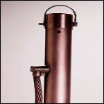
With certain soils it may be very difficult to reach 25 ohms with ground rods. As dereck has stated there are chemical ground rods when installed properly will probably get you there. They are about $600 for the rod alone. The install and rod will probably be more than $1200.00 for each rod.

ChemRod.jpg
 
How was the test performed? That may be your problem. You should have a test report showing a curve having a flat area in the center with multiple readings taken at different distances (52%, 62%, and 72%). If you do not have this type of report your 1st step would to do a proper test before taking corrective actions.

There are 3 way to lower your resistance:

Lengthen the rod, general rule double the length and reduce your readings by 40%

Use multiple rods, add 1 rod 40% reduction, add 2 rods 60% reduection.

Treat the soil, usually with magnesium sulphate or copper sulphate, keep in mind your values may go down for now but may rise later as the treatment washes away.
 
Typically when we do a ground test

1. We perform multiple test in various directions.
2. We take readings a 10, 20, 30, 40, 50, 60, 62, 70, 80, 90 percent of the furthest test electrode. (as Zog noted look for an increase in resistance typically around 62% and higher.
3. The test probes need to be OUT THERE beyond the sphere of influence of the electrode under test, general rule of thumb 10 times the diagonal of the ground grid. But if you do not see an steady increase at 62% (roughly) you may need to go out further with the test electrodes.
4. Driving rods, further apart buys you more, driving more rods will lower the resistance but one rod extra at 50 ohms is not going to buy 25 ohms.

In my experience the majority of these test are performed improperly.
 
dereckbc said:
I kind of suspect something like a Gravel Crusher uses high voltage and will require a low impedance ground to protect the workers.

Dereckbc,

What do you mean by "a low impedance ground to protect the workers"? Could you elaborate little bit?
 
elec_eng said:
Dereckbc,

What do you mean by "a low impedance ground to protect the workers"? Could you elaborate little bit?

Simple Ohm's Law. At high voltages earth can be used as a fault parh. For example a 10-ohm earth at say 13.2 KV develops how much current which will operate a fuse at what size?.

Now try the same 10-ohms at 120 and see what you get? You get a load device on a 15-amp breaker, not a fault right?
That load device could easily be YOU.
 
dereckbc said:
Simple Ohm's Law. At high voltages earth can be used as a fault parh. For example a 10-ohm earth at say 13.2 KV develops how much current which will operate a fuse at what size?.

Now try the same 10-ohms at 120 and see what you get? You get a load device on a 15-amp breaker, not a fault right?
That load device could easily be YOU.

Understood. Wouldn't it be better run an EGC if that is for safety? Certainly, an EGC will have lower resistance.
 
elec_eng said:
Understood. Wouldn't it be better run an EGC if that is for safety? Certainly, an EGC will have lower resistance.
I am talking apples, and you are talking oranges. The OP asked about GES impedance. In an NEC application earth cannot be used as a fault clearing path or a load current path, so yes you have to use a EGC for fault clearing paths with NEC applications

Once you cross over to the NESC or high voltage world all the rules change. I don't know what voltage this rock crusher plant operates at. But I suspect it is high voltage because when I worked as a sub-station engineer we supplied like plants with up to 69KV, and in the utility biz we use earth as both a fault clearing path as well a a load conductor.
 
Last edited:
The rock crusher plants I worked in all were utilized equipment at 4160 and higher. Scary part was little maintenance. DUST everywhere, 2" of dust on the insulators, then there was the water dripping everywhere.
 
Yep same here, rock crusher plants using 4800V cables being dragged all over the place with portable substations, scary stuff, just run it until something stops working.
 
My understanding the MSHA has some odd conceptions of grounding and feels a ground rod will help clear at fault, hence the reason for testing ground rods.
 
Lets say you have a 4160V (About 2400V to ground) system with a 50 ohm load, and a wire makes contact with the metal casing of the load, if you touch the metal frame (or any other part of the buildings metal) and are standing on ground there would be about a 1200V drop across your body if there ground to earth resistance was 50 Ohms.

Same senraio, with a 1 ohm resistamce to ground and the voltage drop across your body would be about 47V drop across your body.

So, you are saying there is no difference between a 1200V shock and a 47V shock?
 
Zog,
Unless you are standing on the rod, in both cases your body will see 2400 volts. Ground rods don't change this unless they clear the fault or you are standing on them.
Don
 
Zog a ground fault forms a simple voltage divider circuit. If the circuit conductors impedance is around 1-ohm (which is a real number) doesn't really matter what the earth ground resistance is in terms of life safety.

Think about this way: If the earth impedance is 1-ohm, and the circuit impedance is 1-ohm. What do you have in terms of a voltage divider? Half!

The only way to truly protect someone from exposure is an equipotential ground plane like a utility tries to make. In other words mount every thing on one big steel plate and bond the heck out of everything. Even that does not cut it. Lets say you did that and achieved a fault path of 1/4 the circuit impedance, it is still a voltage divider of 1 to 4.
 
Last edited:
i dont know about that, it is a matter of a difference between "ground" and earth potentials. Download and read "Getting down to earth" from the Megger website for some examples.
 
dereckbc said:
Think about this way: If the earth impedance is 1-ohm, and the circuit impedance is 1-ohm. What do you have in terms of a voltage divider? Half!

And if the earth impedance is 25 ohms what do you have then? That was the point I was making in my example.
 
Status
Not open for further replies.
Top