I understand. Thank you. I appreciate it. All the data is coming as soon as I get done replyingBy red herring, I mean not relevant. If you adjust something to reduce the voltage to 208V, but don't fix the underlying problem, then it probably won't fix the problem with the blower, on the other hand, if you fix the underlying issue you can keep the 240V for the blower..
The fix for the 'effectively bad' neutral is to use the proper delta:wye transformer, not the wye:wye transformer.
Do keep in mind that the above are my opinion/guesses.
You are using an out of date browser. It may not display this or other websites correctly.
You should upgrade or use an alternative browser.
You should upgrade or use an alternative browser.
Help with getting the right voltage output from a transformer.
- Thread starter mike1061
- Start date
I will look and see if I see any phase that has way more.Agreed I would add post the nameplates for both Trane systems
And look for any large single phase loads in either system that are on the 'open jaw' of the open delta service ( probably the set with that lower voltage )
I have seen a packaged system where two 10kw 240V heat strips (singe phase) ended up on the 'open' phase B-C and by moving the heat strips to A-B (stinger) the voltage regulation of the service was improved.
From what I understand from a few heating guys, the VFD is because they put them in to meet the energy code. That all the manufacturers are doing it. They don’t want to make a special unit just for Chicago’s bad electrical grid. In one instance another heating guy I know, just put in a different blower.Question,
Does the unit have to have the VFD control the motor? It seems to be that the VFD is the issue.
This company says you can not do that here. In fact, I’m told, the newer models have a blower that will not allow me to intercept the wires like I did for this job. I have not actually seen one.
And yes it seems to be just the VFD blower that has the problem. I’m told the electrical affects just the VFD part. That the actual blower works fine on this electrical supply.
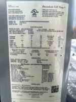
Here is the current data from today about 3:30 pm.
This is the problem unit:
Averaging meter
Input, 125,125,217, 250,250,226
Output, 140,140,140, 253,253,228
True rms
Input 123, 123, 215
246, 247, 248
Output 143, 146, 141
247, 247, 250,
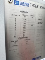
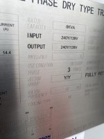
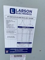
The picture is the unit name part. I added the transformer labels so you would have all the data right in front of you
This is the problem unit:
Averaging meter
Input, 125,125,217, 250,250,226
Output, 140,140,140, 253,253,228
True rms
Input 123, 123, 215
246, 247, 248
Output 143, 146, 141
247, 247, 250,
The picture is the unit name part. I added the transformer labels so you would have all the data right in front of you
Attachments

Last edited:
winnie
Senior Member
- Location
- Springfield, MA, USA
- Occupation
- Electric motor research
Question,
Does the unit have to have the VFD control the motor? It seems to be that the VFD is the issue.
I agree, the VFD is the issue. And the VFD _could_ have been designed to work just fine with high leg delta power; the thing is has a rectifier front end to convert the incoming AC to DC. But that is a whole 'nother box of fish to discuss
")
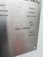
This is the info for the first unit, which seems to be working
Today also at around 3:30
averaging meter
Input 129, 117, 129
236, 237, 245,
Output 114, 114, 189
250, 250, 226
True rms,
Input, 111, 111, 193
247, 246, 248
Output 125, 125, 125,
239, 241, 241
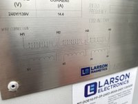
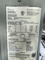
The pictures are of the unit name plate and the transformer label. This one only has one
Today also at around 3:30
averaging meter
Input 129, 117, 129
236, 237, 245,
Output 114, 114, 189
250, 250, 226
True rms,
Input, 111, 111, 193
247, 246, 248
Output 125, 125, 125,
239, 241, 241
The pictures are of the unit name plate and the transformer label. This one only has one
Attachments
- Location
- Wisconsin
- Occupation
- PE (Retired) - Power Systems
It would help if you identified what conductors each measurement is from.Here is the current data from today about 3:30 pm.
This is the problem unit:
Averaging meter
Input, 125,125,217, 250,250,226
Output, 140,140,140, 253,253,228
True rms
Input 123, 123, 215
246, 247, 248
Output 143, 146, 141
247, 247, 250,
The picture is the unit name part. I added the transformer labels so you would have all the data right in front of you
If the low voltage 226V is on phases B-C you may be experiencing imbalance due to too many single phase loads.
Ok. I’ll go back and get that. I don’t think they have anything else that is 3 phase. There are few 240 1 phase appliances, I think. 4 offices, an event space, a large kitchen and an artist studio. Most of which have little use. They have a 400 amp 3 phase service. At 3:30 there were 5 people all using computers, that’s it.It would help if you identified what conductors each measurement is from.
If the low voltage 226V is on phases B-C you may be experiencing imbalance due to too many single phase loads.
- Location
- Wisconsin
- Occupation
- PE (Retired) - Power Systems
Is their's a dedicated utility transformer bank or is it shared?They have a 400 amp 3 phase service. At 3:30 there were 5 people all using computers, that’s it.
The utility transformers are almost certainly shared with the school across the alley. There’s nothing else on the block. I could look and see when I go test the lines again.Is their's a dedicated utility transformer bank or is it shared?
Thanks
kwired
Electron manager
- Location
- NE Nebraska
- Occupation
- EC
I was thinking that and mentioned it in an earlier post, but also mentioned that it probably should drag down the high leg to neutral voltage though his readings don't show that happening.If the low voltage 226V is on phases B-C you may be experiencing imbalance due to too many single phase loads.
- Location
- San Francisco Bay Area, CA, USA
- Occupation
- Electrical Engineer
That original comment about the VFD not providing full output because the voltage needs to be 208V is pure unadulterated bovine excretia….
winnie
Senior Member
- Location
- Springfield, MA, USA
- Occupation
- Electric motor research
I wonder though: if because of the particular transformer involved, if the drive is shutting down because of excessive L-N voltage, and if a transformer with the same arrangement but lower output voltage would 'work'.That original comment about the VFD not providing full output because the voltage needs to be 208V is pure unadulterated bovine excretia….
Not IMHO the correct solution, but it could plausibly be one of those cases where something works even though the reason that it works isn't understood.
Just to be clear: I am not advocating going down this path.
- Location
- Wisconsin
- Occupation
- PE (Retired) - Power Systems
According to the OP, the VFD was misbehaving first. Adding the Y-Y transformer did not solve the original problem.I wonder though: if because of the particular transformer involved, if the drive is shutting down because of excessive L-N voltage,
That is with Trane is saying. Do you have any ideas what is wrong or what I can do to fix this? They replaced everything involved, or so they say, I wasn’t there.That original comment about the VFD not providing full output because the voltage needs to be 208V is pure unadulterated bovine excretia….
Thanks
Mike
This is true. One question is, is this wye to wye or delta to wye (which is what I thought I had).According to the OP, the VFD was misbehaving first. Adding the Y-Y transformer did not solve the original problem.
Thanks
Mike
What would be a better solution? At the moment, I’m going to get more readings to help you guys tell if it’s delta to wye or wye to wye.I wonder though: if because of the particular transformer involved, if the drive is shutting down because of excessive L-N voltage, and if a transformer with the same arrangement but lower output voltage would 'work'.
Not IMHO the correct solution, but it could plausibly be one of those cases where something works even though the reason that it works isn't understood.
Just to be clear: I am not advocating going down this path.
Edited to ask, I don’t quite get the excessive l-n voltage because there is no neutral. The XO of the transformer is connected to the metal case.
Thanks
Mike
kwired
Electron manager
- Location
- NE Nebraska
- Occupation
- EC
XO is the neutral of the secondary system. You simply don't have any neutral loads to supply so it essentially is just grounded and then has the equipment grounding conductor connected to it.What would be a better solution? At the moment, I’m going to get more readings to help you guys tell if it’s delta to wye or wye to wye.
Edited to ask, I don’t quite get the excessive l-n voltage because there is no neutral. The XO of the transformer is connected to the metal case.
Thanks
Mike
- Location
- Wisconsin
- Occupation
- PE (Retired) - Power Systems
The nameplate clearly shows it is not the Delta-Wye you wanted.This is true. One question is, is this wye to wye or delta to wye (which is what I thought I had).
Thanks
Mike
So the unit that is working has unbalanced voltage going to it, but the unit that doesn't work has balanced voltages?
That seems to imply the voltage isn't the problem, or at least not the problem keeping the VFD from running at full speed.
I wonder if the VFD just has some parameters set wrong? Also wondering if the HVAC controls just aren't calling for full output? For example, maybe the temp. differential just isn't enough, or maybe the thermostat or a sensor isn't reading correctly?