crossman
Senior Member
- Location
- Southeast Texas
I have been enjoying the 4-wire delta thread. I have a question, but didn't want to lead the topic astray, so I started a new thread.
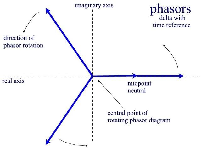
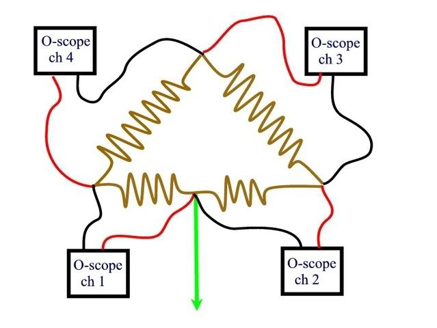
In the first diagram, there isn't really a reference, except for time itself. I say that because there is no single place in the diagram that we are keeping involved in all voltage measurements. We can take an o-scope with 4 isolated channels and compare the sine waves for "out of phase" conditions compared to the other voltage graphs. We are just measuring voltages around the delta and being consistent with the polarity of each o-scope channel.
I can understand the RMS vectors which would arise from this. They would simply be arrows drawn on the windings with, say, the heads at the black leads and the tails at the red leads. Simple enough, and the two vectors at the bottom of the drawing that involve the midpoint "neutral" would be drawn the same direction = in phase.
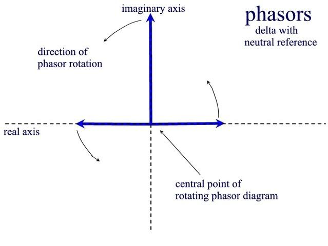
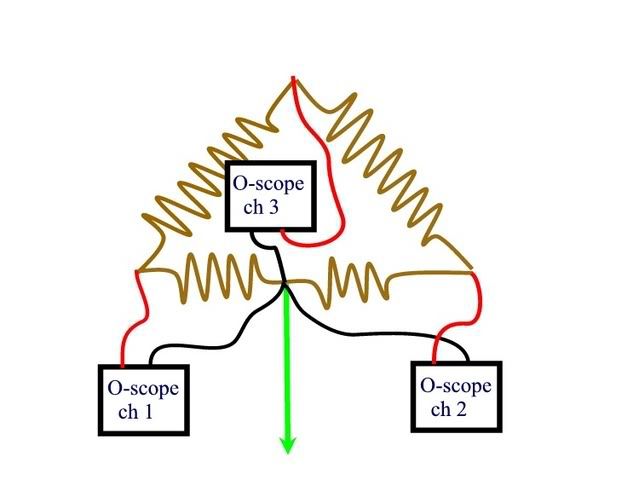
But in the next diagram, if we make all measurements in reference to the neutral, then there are actually only three places we can get voltage readings, not four as in the diagram above. What would the vectors look like if we always kept the black lead of each o-scope channel on the neutral? We would only have 3 o-scope graphs. It seems that there could only be 3 vectors. What would the vectors look like?
In the first diagram, there isn't really a reference, except for time itself. I say that because there is no single place in the diagram that we are keeping involved in all voltage measurements. We can take an o-scope with 4 isolated channels and compare the sine waves for "out of phase" conditions compared to the other voltage graphs. We are just measuring voltages around the delta and being consistent with the polarity of each o-scope channel.
I can understand the RMS vectors which would arise from this. They would simply be arrows drawn on the windings with, say, the heads at the black leads and the tails at the red leads. Simple enough, and the two vectors at the bottom of the drawing that involve the midpoint "neutral" would be drawn the same direction = in phase.
But in the next diagram, if we make all measurements in reference to the neutral, then there are actually only three places we can get voltage readings, not four as in the diagram above. What would the vectors look like if we always kept the black lead of each o-scope channel on the neutral? We would only have 3 o-scope graphs. It seems that there could only be 3 vectors. What would the vectors look like?