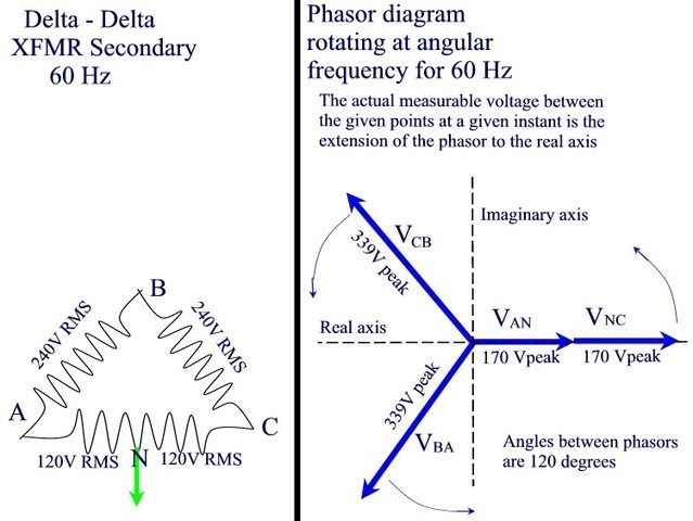
Hi-leg Delta xfmr reference?

Status
Not open for further replies.
crossman said:
Now, say we have a high-leg delta system. Would it be proper to show the voltage phasor from A to C as being split by the Neutral as in the following diagram?

deltaneutral.jpg

This is not correct. Now that you have the concept of phasors down, let's work on the notation a little bit.

I'll have to look at the labels but as far as the location of the VNC phasor, it would be located directly on top of the VAN phasor. Read my other post and let me know if this is not clear.

[edit: grabbed wrong quote,. I grabbed rattus and I meant to get crossman I incorrectly had the following in here:

rattus said:
First off, you are showing a wye diagram. Connect all the arrows head to tail to form an equilateral triangle.

Second, these are static phasors and their magnitude is 120Vrms. It is confusing to provide peak values.

Yes, the head to tail connection of the 120V phasors is correct, but it is not the only correct configuration.
 
no can do

no can do

rattus said:
First off, you are showing a wye diagram. Connect all the arrows head to tail to form an equilateral triangle.

Second, these are static phasors and their magnitude is 120Vrms. It is confusing to provide peak values.

Yes, the head to tail connection of the 120V phasors is correct, but it is not the only correct configuration.

I disagree with this. See my prior post labled "don't confuse circuit and phasor diagrams" post and get back to me.

[edit: spelling]
 
Last edited:
mivey said:
As for the phasor diagram, an open-type phasor diagram is the preferred method. Also, don't get confused and mix a phasor diagram with a circuit diagram. They are not the same thing.

A closed-type phasor diagram may LOOK like the circuit diagram but a circuit diagram and phasor diagram serve two different functions.

Most protective relay manufacturers use the standard that the arrows and subscripts are the actual or assumed direction of current flow during the positive half-cycle of the ac wave. A notation of Vab would have an voltage arrow pointing from b to a and a current arrow pointing from a to b and indicates a voltage drop from a to b.

A circuit diagram uses these notations when showing the location and assumed directions of current and voltage drops. A phasor diagram shows the current and voltage magnitudes and phase relations.

For a delta circuit, think about the difference in what you would see in the closed type phasor diagram and what would appear on the delta circuit diagram. For example, lets consider a phasor diagram with a on the x-axis, b oriented 120 degrees clockwise, and c oriented 120 degrees counter-clockwise. Use this same a-b-c layout for the delta circuit. The arrow on the phasor diagram would be pointing from b to a and would be labeled Vab. On the circuit diagram, this would be a voltage drop from a to b and the arrow would be reversed. You can see the same can be said for the phase to neutral arrows.

The open-type phasor diagram avoids this confusion and that is why it is the preferred method

crossman, you could probably draw a nice picture of this.

I would say that the head to tail diagram is standard for the delta and this corresponds to the schematic although said schematic might not be shaped like a delta or oriented the same way.

Likewise the wye diagram would have the arrows pointing away from the neutral, and this too corresponds to the schematic.

The magnitude of a static phasor must an RMS value in order for,

Pa=VI

The magnitude of a rotating phasor must be a peak value for the instantaneous values to be correct. although we would not use rotating phasors in steady state analysis.

Vab means the voltage at a with respect to b, in other words, black on b, red on a.
 
rattus said:
I would say that the head to tail diagram is standard for the delta and this corresponds to the schematic although said schematic might not be shaped like a delta or oriented the same way.

Likewise the wye diagram would have the arrows pointing away from the neutral, and this too corresponds to the schematic.
Let me get a diagram drawn so we can compare notes.

rattus said:
The magnitude of a static phasor must an RMS value in order for,

Pa=VI
I'm not sure I'm following this. All of this is solved with sqrt(2). I don't see it as a must, just a preference. I would agree that one is certainly "yummier" than the other.

rattus said:
The magnitude of a rotating phasor must be a peak value for the instantaneous values to be correct. although we would not use rotating phasors in steady state analysis.
Same difference as in the rms case.

rattus said:
Vab means the voltage at a with respect to b, in other words, black on b, red on a.
I see that voltage drop from a to b = voltage rise from b to a. You can also express it the way you did. I don't see a significant difference, or did I miss a point?
 
mivey said:
Let me get a diagram drawn so we can compare notes.


I'm not sure I'm following this. All of this is solved with sqrt(2). I don't see it as a must, just a preference. I would agree that one is certainly "yummier" than the other.


Same difference as in the rms case.


I see that voltage drop from a to b = voltage rise from b to a. You can also express it the way you did. I don't see a significant difference, or did I miss a point?

We use RMS values so we don't have to use sqrt(2) or its inverse. Yummier.

You are right on the rises and drops.

Now can you see any difference between negating a phasor and subtracting that phasor?
 
just math

just math

rattus said:
We use RMS values so we don't have to use sqrt(2) or its inverse. Yummier.

You are right on the rises and drops.

Now can you see any difference between negating a phasor and subtracting that phasor?

With the way I think you are using phasors, no...it is just math.
 
All righty then. Let's see if this picture makes sense. The assumptions for labeling and arrow directions are as noted.
phasorvscircuitdiagram.jpg
 
mivey said:
All righty then. Let's see if this picture makes sense. The assumptions for labeling and arrow directions are as noted.

I vote for these diagrams as the basis for continuing discussions. It makes no difference which one but you must be consistent in its use. My background (actually my 1974 textbook and my 1969 engineering handbook) favors the "open phasor" diagrams.
 
Corrected diagram

Corrected diagram

I had real notation problems on the previous diagram. I'm trying to show that the corners created by the closed phasors are not the same as the terminal points on the transformer. If you can think of a better example or if you note anything wrong in this updated diagram, please let me know.

[edit: I put the current in at 90 degrees lagging for the 3W to illustrate my point. The 4W, by virtue of there being no direct high-leg to neutral path, already makes this point. For the delta, moving the labels away from the arrows is clearer. Thanks for the feedback so far.]
 
Last edited:
Re-stated the correct way

Re-stated the correct way

I'm correcting the earlier post. The point was to show that while the phasor and circuit diagrams are shaped the same, the corners on the phasor diagram are not the terminals on the transformer.

Restated with corrections in bold caps:
As for the phasor diagram, an open-type phasor diagram is the preferred method. Also, don't get confused and mix a phasor diagram with a circuit diagram. They are not the same thing.

A closed-type phasor diagram may LOOK like the circuit diagram but a circuit diagram and phasor diagram serve two different functions.

Most protective relay manufacturers use the standard that the arrows and subscripts are the actual or assumed direction of current flow during the positive half-cycle of the ac wave. A notation of Vab would have an voltage arrow pointing from b to a and a current arrow pointing from a to b and indicates a voltage drop from a to b.

A circuit diagram uses these notations when showing the location and assumed directions of current and voltage drops. A phasor diagram shows the current and voltage magnitudes and phase relations.

For a delta circuit, think about the difference in what you would see in the closed type phasor diagram and what would appear on the delta circuit diagram. For example, lets consider a phasor diagram with a on the x-axis, b oriented 120 degrees clockwise, and c oriented 120 degrees counter-clockwise. Use this same a-b-c layout for the delta circuit. The VOLTAGE arrow on the phasor diagram would be pointing from b to a and would be labeled Vab. On the circuit diagram, this would be a voltage drop from a to b and the CURRENT arrow would be reversed. You can see the same can be said for the phase to neutral arrows.

The open-type phasor diagram avoids this confusion and that is why it is the preferred method
 
Status
Not open for further replies.
Top